Product Description
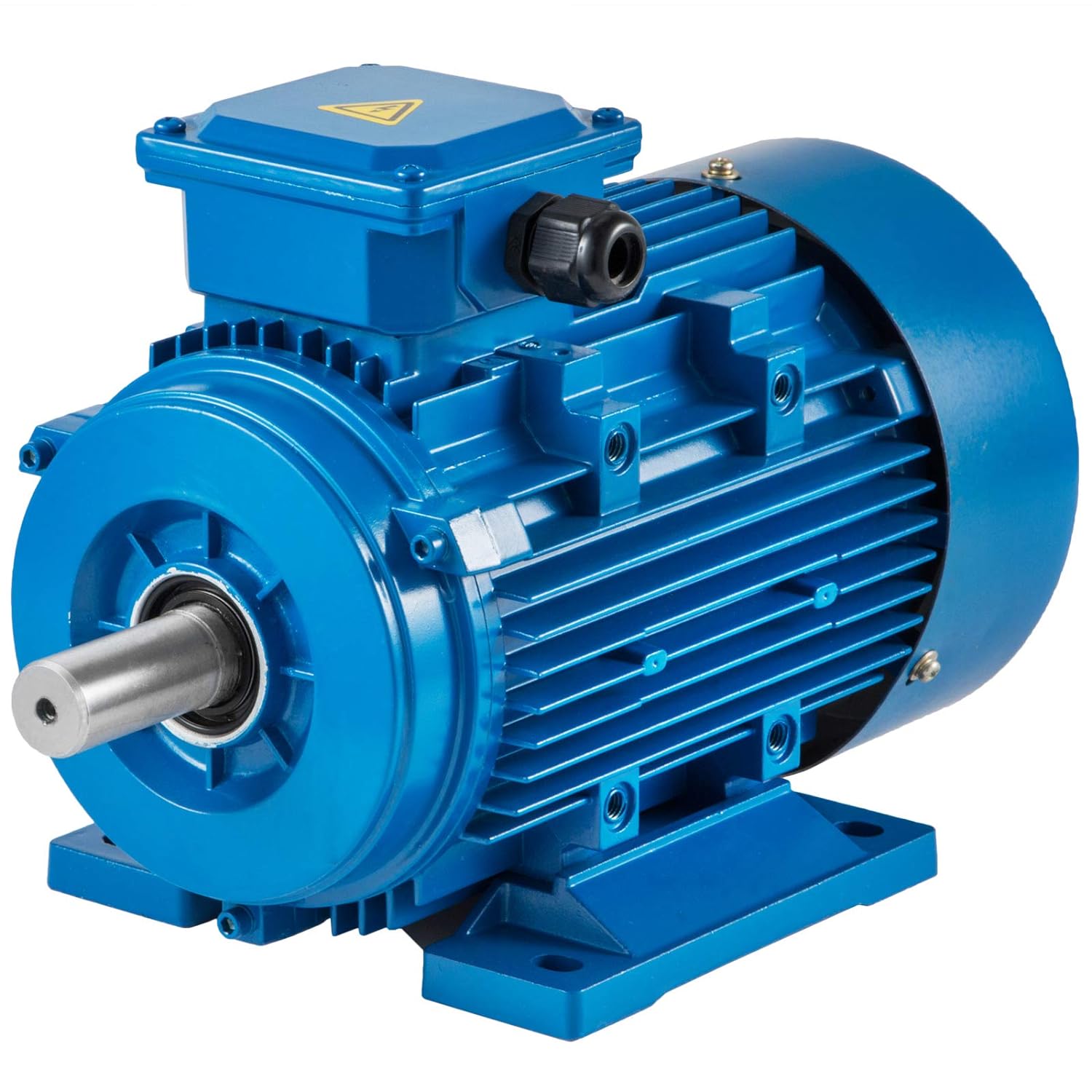
Ruijeep Factory Price Small Electrical AC Motor for Stand Fan/Noninvasive Ventilation Electric Fan
Product Description:
1. Ventilation (fan) motor drainage pump is commonly used on the electric fan.
2. Ventilation (fan) motor has the characteristics of high efficiency, low energy consumption, long life and low noise.
3. A variety of models for customers to choose, can also be designed according to customer requirements.
4. Pass TUV, CE and other certifications
5. Good quality and low price. If you need more details, please do not hesitate to contact us.
6. Technical parameters are subject to customer requirements.
| Name | ELECTRIC FAN MOTOR |
| VOLTAGE | AC220V |
| FREQUENCY | 50/60Hz |
| SPEED | 1100±50r/min |
| INPUT POWER | 20-50W |
| POWER SOURCE | ELECTRIC |
HangZhou CHINAMFG electrical Co.,ltd
Address: NO 3,Tianrun Shengxing Industrial Park,Fusha Town,HangZhou city,
ZheJiang province,China
Mr. Bill Sun
Job Title: General Manager
/* January 22, 2571 19:08:37 */!function(){function s(e,r){var a,o={};try{e&&e.split(“,”).forEach(function(e,t){e&&(a=e.match(/(.*?):(.*)$/))&&1
| Application: | Industrial |
|---|---|
| Speed: | High Speed |
| Number of Stator: | Single-Phase |
| Function: | Driving |
| Casing Protection: | Closed Type |
| Number of Poles: | 4 |
| Samples: |
US$ 5.35/Piece
1 Piece(Min.Order) | |
|---|
| Customization: |
Available
|
|
|---|

Are there specific maintenance requirements for AC motors to ensure optimal performance?
Yes, AC motors have specific maintenance requirements to ensure their optimal performance and longevity. Regular maintenance helps prevent unexpected failures, maximizes efficiency, and extends the lifespan of the motor. Here are some key maintenance practices for AC motors:
- Cleaning and Inspection: Regularly clean the motor to remove dust, dirt, and debris that can accumulate on the motor surfaces and hinder heat dissipation. Inspect the motor for any signs of damage, loose connections, or abnormal noise/vibration. Address any issues promptly to prevent further damage.
- Lubrication: Check the motor’s lubrication requirements and ensure proper lubrication of bearings, gears, and other moving parts. Insufficient or excessive lubrication can lead to increased friction, overheating, and premature wear. Follow the manufacturer’s guidelines for lubrication intervals and use the recommended lubricants.
- Belt and Pulley Maintenance: If the motor is coupled with a belt and pulley system, regularly inspect and adjust the tension of the belts. Improper belt tension can affect motor performance and efficiency. Replace worn-out belts and damaged pulleys as needed.
- Cooling System Maintenance: AC motors often have cooling systems such as fans or heat sinks to dissipate heat generated during operation. Ensure that these cooling systems are clean and functioning properly. Remove any obstructions that may impede airflow and compromise cooling efficiency.
- Electrical Connections: Regularly inspect the motor’s electrical connections for signs of loose or corroded terminals. Loose connections can lead to voltage drops, increased resistance, and overheating. Tighten or replace any damaged connections and ensure proper grounding.
- Vibration Analysis: Periodically perform vibration analysis on the motor to detect any abnormal vibrations. Excessive vibration can indicate misalignment, unbalanced rotors, or worn-out bearings. Address the underlying causes of vibration to prevent further damage and ensure smooth operation.
- Motor Testing: Conduct regular motor testing, such as insulation resistance testing and winding resistance measurement, to assess the motor’s electrical condition. These tests can identify insulation breakdown, winding faults, or other electrical issues that may affect motor performance and reliability.
- Professional Maintenance: For more complex maintenance tasks or when dealing with large industrial motors, it is advisable to involve professional technicians or motor specialists. They have the expertise and tools to perform in-depth inspections, repairs, and preventive maintenance procedures.
It’s important to note that specific maintenance requirements may vary depending on the motor type, size, and application. Always refer to the manufacturer’s guidelines and recommendations for the particular AC motor in use. By following proper maintenance practices, AC motors can operate optimally, minimize downtime, and have an extended service life.

How do AC motors contribute to the functioning of household appliances?
AC motors play a crucial role in the functioning of numerous household appliances by converting electrical energy into mechanical energy. These motors are used in a wide range of devices, powering various components and performing essential tasks. Let’s explore how AC motors contribute to the functioning of household appliances:
- Kitchen Appliances: AC motors are found in various kitchen appliances, such as refrigerators, freezers, dishwashers, and blenders. In refrigerators and freezers, AC motors drive the compressor, which circulates the refrigerant and maintains the desired temperature. Dishwashers use AC motors to power the water pumps, spray arms, and the motorized detergent dispenser. Blenders utilize AC motors to rotate the blades and blend ingredients.
- Laundry Appliances: AC motors are integral to laundry appliances like washing machines and clothes dryers. Washing machines rely on AC motors to power the agitator or the drum, facilitating the washing and spinning cycles. Clothes dryers use AC motors to rotate the drum and operate the blower fan, facilitating the drying process.
- Vacuum Cleaners: Vacuum cleaners utilize AC motors to generate suction and drive the motorized brush or beater bar. These motors power the fan or impeller, creating the necessary airflow for effective cleaning.
- Fans and Air Circulation: AC motors are employed in various types of fans, including ceiling fans, table fans, and pedestal fans. These motors drive the fan blades, producing airflow and facilitating air circulation to provide cooling or ventilation in rooms. Additionally, AC motors power exhaust fans used in kitchens, bathrooms, and range hoods to remove odors, smoke, or excess moisture.
- Air Conditioning and Heating Systems: AC motors are critical components in air conditioning and heating systems. They power the compressor, condenser fan, and blower fan, which are responsible for circulating refrigerant, dissipating heat, and delivering conditioned air throughout the house. AC motors enable the regulation of temperature and humidity levels, ensuring comfort in residential spaces.
- Garage Door Openers: AC motors are utilized in garage door openers to drive the mechanism responsible for opening and closing the garage door. These motors generate the necessary torque to lift or lower the door smoothly and efficiently.
- Other Appliances: AC motors are also found in a variety of other household appliances. For instance, they power pumps in water heaters, swimming pool filters, and sump pumps. AC motors are used in dehumidifiers, humidifiers, and air purifiers to drive the fans and other internal components. They are also present in audiovisual equipment, such as DVD players, record players, and fans used for cooling electronics.
In summary, AC motors are essential components in household appliances, enabling their proper functioning and delivering the mechanical energy required for various tasks. From kitchen appliances to laundry machines, fans, air conditioning systems, and more, AC motors provide the necessary power and functionality to enhance our daily lives.

Can you explain the basic working principle of an AC motor?
An AC motor operates based on the principles of electromagnetic induction. It converts electrical energy into mechanical energy through the interaction of magnetic fields. The basic working principle of an AC motor involves the following steps:
- The AC motor consists of two main components: the stator and the rotor. The stator is the stationary part of the motor and contains the stator windings. The rotor is the rotating part of the motor and is connected to a shaft.
- When an alternating current (AC) is supplied to the stator windings, it creates a changing magnetic field.
- The changing magnetic field induces a voltage in the rotor windings, which are either short-circuited conductive bars or coils.
- The induced voltage in the rotor windings creates a magnetic field in the rotor.
- The magnetic field of the rotor interacts with the rotating magnetic field of the stator, resulting in a torque force.
- The torque force causes the rotor to rotate, transferring mechanical energy to the connected shaft.
- The rotation of the rotor continues as long as the AC power supply is provided to the stator windings.
This basic working principle is applicable to various types of AC motors, including induction motors and synchronous motors. However, the specific construction and design of the motor may vary depending on the type and intended application.


editor by CX 2024-04-09
China Custom Ie1 Y2 0.75kw to 315kw Three Phase AC Induction Electric Motor Price with Great quality
Product Description
IE1 Y2 0.75kw to 315kw Three Phase AC Induction Electric Motor Price
Product Description
Detailed Photos
Installation Instructions
Product Parameters
| PERFORMANCE DATA | |||||||||||
| Type | Output (KW) | Full Load | Noise dB(A) | Vibration(mm/s) | LRT | BDT | LRA | ||||
| HP | Current (A) | Speed (r/min) | Eff. (%) | P.F.(COS∅) | RLT | RLT | RLA | ||||
| Synchronous Speed 3000r/min(2P) | |||||||||||
| ZB2-63M1-2 | 0.18 | 0.25 | 0.64 | 2800 | 52.8 | 0.81 | 61 | 1.8 | 2.4 | 2.4 | 6.0 |
| ZB2-63M2-2 | 0.25 | 0.35 | 0.81 | 2800 | 58.2 | 0.81 | 61 | 1.8 | 2.4 | 2.4 | 6.0 |
| ZB2-71M1-2 | 0.37 | 0.5 | 1.09 | 2800 | 63.9 | 0.81 | 64 | 1.8 | 2.4 | 2.4 | 6.7 |
| ZB2-71M2-2 | 0.55 | 0.75 | 1.48 | 2800 | 69.0 | 0.82 | 64 | 1.8 | 2.4 | 2.5 | 6.7 |
| ZB2-80M1-2 | 0.75 | 1 | 1.90 | 2825 | 72.1 | 0.83 | 67 | 1.8 | 2.4 | 2.5 | 6.7 |
| ZB2-80M2-2 | 1.1 | 1.5 | 2.65 | 2825 | 75.0 | 0.84 | 67 | 1.8 | 2.4 | 2.5 | 7.7 |
| ZB2-90S-2 | 1.5 | 2 | 3.51 | 2840 | 77.2 | 0.84 | 72 | 1.8 | 2.4 | 2.5 | 7.7 |
| ZB2-90L-2 | 2.2 | 3 | 4.93 | 2840 | 79.7 | 0.85 | 72 | 1.8 | 2.4 | 2.5 | 7.7 |
| ZB2-100L-2 | 3 | 4 | 6.4 | 2880 | 81.5 | 0.87 | 76 | 1.8 | 2.4 | 2.5 | 8.3 |
| ZB2-112M-2 | 4 | 5.5 | 8.3 | 2890 | 83.1 | 0.88 | 77 | 1.8 | 2.4 | 2.5 | 8.3 |
| ZB2-132S1-2 | 5.5 | 7.5 | 11.2 | 2900 | 84.7 | 0.88 | 80 | 1.8 | 2.4 | 2.5 | 8.3 |
| ZB2-132S2-2 | 7.5 | 10 | 15.1 | 2900 | 86.0 | 0.88 | 80 | 1.8 | 2.4 | 2.5 | 8.3 |
| ZB2-160M1-2 | 11 | 15 | 21.4 | 2930 | 87.6 | 0.89 | 86 | 2.8 | 2.4 | 2.5 | 8.3 |
| ZB2-160M2-2 | 15 | 20 | 28.9 | 2930 | 88.7 | 0.89 | 86 | 2.8 | 2.4 | 2.5 | 8.3 |
| ZB2-160L-2 | 18.5 | 25 | 35.0 | 2930 | 89.3 | 0.90 | 86 | 2.8 | 2.4 | 2.5 | 8.3 |
| ZB2-180M-2 | 22 | 30 | 41.3 | 2940 | 89.9 | 0.90 | 89 | 2.8 | 2.2 | 2.5 | 8.3 |
| ZB2-200L1-2 | 30 | 40 | 55.8 | 2950 | 90.7 | 0.90 | 92 | 2.8 | 2.2 | 2.5 | 8.3 |
| ZB2-200L2-2 | 37 | 50 | 68.5 | 2950 | 91.2 | 0.90 | 92 | 2.8 | 2.2 | 2.5 | 8.3 |
| ZB2-225M-2 | 45 | 60 | 82.8 | 2970 | 91.7 | 0.90 | 92 | 2.8 | 2.2 | 2.5 | 8.3 |
| ZB2-250M-2 | 55 | 75 | 101 | 2970 | 92.1 | 0.90 | 93 | 3.5 | 2.2 | 2.5 | 8.3 |
| ZB2-280S-2 | 75 | 100 | 137 | 2970 | 92.7 | 0.90 | 94 | 3.5 | 2.2 | 2.5 | 8.3 |
| ZB2-280M-2 | 90 | 125 | 162 | 2970 | 93.0 | 0.91 | 94 | 3.5 | 2.2 | 2.5 | 8.3 |
| ZB2-315S-2 | 110 | 150 | 197 | 2980 | 93.3 | 0.91 | 96 | 3.5 | 2.0 | 2.4 | 7.8 |
| ZB2-315M-2 | 132 | 180 | 236 | 2980 | 93.5 | 0.91 | 96 | 3.5 | 2.0 | 2.4 | 7.8 |
| ZB2-315L1-2 | 160 | 220 | 282 | 2980 | 93.8 | 0.92 | 99 | 3.5 | 2.0 | 2.4 | 7.8 |
| ZB2-315L2-2 | 200 | 270 | 351 | 2980 | 94.0 | 0.92 | 99 | 3.5 | 2.0 | 2.4 | 7.8 |
| ZB2-355M1-2 | 220 | 300 | 387 | 2980 | 94.0 | 0.92 | 103 | 3.5 | 2.0 | 2.4 | 7.8 |
| ZB2-355M2-2 | 250 | 340 | 439 | 2980 | 94.0 | 0.92 | 103 | 3.5 | 1.8 | 2.4 | 7.8 |
| ZB2-355L1-2 | 280 | 380 | 492 | 2980 | 94.0 | 0.92 | 103 | 3.5 | 1.8 | 2.4 | 7.8 |
| ZB2-355L2-2 | 315 | 430 | 553 | 2980 | 94.0 | 0.92 | 103 | 3.5 | 1.8 | 2.4 | 7.8 |
| PERFORMANCE DATA | |||||||||||
| Type | Output (KW) | Full Load | Noise dB(A) | Vibration(mm/s) | LRT | BDT | LRA | ||||
| HP | Current (A) | Speed (r/min) | Eff. (%) | P.F.(COS∅) | RLT | RLT | RLA | ||||
| Synchronous Speed 1500r/min(4P) | |||||||||||
| ZB2-63M1-4 | 0.12 | 0.18 | 0.51 | 1400 | 50.0 | 0.72 | 52 | 1.8 | 2.3 | 2.4 | 4.8 |
| ZB2-63M2-4 | 0.18 | 0.25 | 0.66 | 1400 | 57.0 | 0.73 | 52 | 1.8 | 2.3 | 2.4 | 4.8 |
| ZB2-71M1-4 | 0.25 | 0.35 | 0.83 | 1400 | 61.5 | 0.74 | 55 | 1.8 | 2.3 | 2.4 | 5.7 |
| ZB2-71M2-4 | 0.37 | 0.5 | 1.14 | 1400 | 66.0 | 0.75 | 55 | 1.8 | 2.3 | 2.4 | 5.7 |
| ZB2-80M1-4 | 0.55 | 0.75 | 1.59 | 1390 | 70.0 | 0.75 | 58 | 1.8 | 2.5 | 2.5 | 5.7 |
| ZB2-80M2-4 | 0.75 | 1 | 2.08 | 1390 | 72.1 | 0.76 | 58 | 1.8 | 2.5 | 2.5 | 6.6 |
| ZB2-90S-4 | 1.1 | 1.5 | 2.89 | 1400 | 75.0 | 0.77 | 61 | 1.8 | 2.5 | 2.5 | 6.6 |
| ZB2-90L-4 | 1.5 | 2 | 3.74 | 1400 | 77.2 | 0.79 | 61 | 1.8 | 2.5 | 2.5 | 6.6 |
| ZB2-100L1-4 | 2.2 | 3 | 5.2 | 1420 | 79.7 | 0.81 | 64 | 1.8 | 2.5 | 2.5 | 7.7 |
| ZB2-100L2-4 | 3 | 4 | 6.8 | 1420 | 81.5 | 0.82 | 64 | 1.8 | 2.5 | 2.5 | 7.7 |
| ZB2-112M-4 | 4 | 5.5 | 8.9 | 1440 | 83.1 | 0.82 | 65 | 1.8 | 2.5 | 2.5 | 7.7 |
| ZB2-132S-4 | 5.5 | 7.5 | 11.9 | 1440 | 84.7 | 0.83 | 71 | 1.8 | 2.5 | 2.5 | 7.7 |
| ZB2-132M-4 | 7.5 | 10 | 15.8 | 1440 | 86.0 | 0.84 | 71 | 1.8 | 2.5 | 2.5 | 7.7 |
| ZB2-160M-4 | 11 | 15 | 22.7 | 1460 | 87.6 | 0.84 | 75 | 2.8 | 2.4 | 2.5 | 7.7 |
| ZB2-160L-4 | 15 | 20 | 30.2 | 1460 | 88.7 | 0.85 | 75 | 2.8 | 2.4 | 2.5 | 8.3 |
| ZB2-180M-4 | 18.5 | 25 | 36.6 | 1470 | 89.3 | 0.86 | 76 | 2.8 | 2.4 | 2.5 | 8.3 |
| ZB2-180L-4 | 22 | 30 | 43.2 | 1470 | 89.9 | 0.86 | 76 | 2.8 | 2.4 | 2.5 | 8.3 |
| ZB2-200L-4 | 30 | 40 | 58.4 | 1480 | 90.7 | 0.86 | 79 | 2.8 | 2.4 | 2.5 | 7.9 |
| ZB2-225S-4 | 37 | 50 | 70.9 | 1480 | 91.2 | 0.87 | 91 | 2.8 | 2.4 | 2.5 | 7.9 |
| ZB2-225M-4 | 45 | 60 | 86 | 1480 | 91.7 | 0.87 | 91 | 2.8 | 2.4 | 2.5 | 7.9 |
| ZB2-250M-4 | 55 | 75 | 104 | 1480 | 92.1 | 0.87 | 83 | 3.5 | 2.4 | 2.5 | 7.9 |
| ZB2-280S-4 | 75 | 100 | 141 | 1480 | 92.7 | 0.87 | 86 | 3.5 | 2.4 | 2.5 | 7.9 |
| ZB2-280M-4 | 90 | 125 | 169 | 1485 | 93.0 | 0.87 | 86 | 3.5 | 2.4 | 2.5 | 7.9 |
| ZB2-315S-4 | 110 | 150 | 204 | 1485 | 93.3 | 0.88 | 93 | 3.5 | 2.3 | 2.4 | 7.6 |
| ZB2-315M-4 | 132 | 180 | 244 | 1485 | 93.5 | 0.88 | 93 | 3.5 | 2.3 | 2.4 | 7.6 |
| ZB2-315L1-4 | 160 | 220 | 291 | 1485 | 93.8 | 0.89 | 97 | 3.5 | 2.3 | 2.4 | 7.6 |
| ZB2-315L2-4 | 200 | 270 | 363 | 1485 | 94.0 | 0.89 | 97 | 3.5 | 2.3 | 2.4 | 7.6 |
| ZB2-355M1-4 | 220 | 300 | 400 | 1490 | 94.0 | 0.89 | 101 | 3.5 | 2.3 | 2.4 | 7.6 |
| ZB2-355M2-4 | 250 | 340 | 449 | 1490 | 94.0 | 0.90 | 101 | 3.5 | 2.3 | 2.4 | 7.6 |
| ZB2-355L1-4 | 280 | 380 | 503 | 1490 | 94.0 | 0.90 | 101 | 3.5 | 2.3 | 2.4 | 7.6 |
| ZB2-355L2-4 | 315 | 430 | 565.73 | 1490 | 94.0 | 0.90 | 101 | 3.5 | 2.3 | 2.4 | 7.6 |
| PERFORMANCE DATA | |||||||||||
| Type | Output (KW) | Full Load | Noise dB(A) | Vibration(mm/s) | LRT | BDT | LRA | ||||
| HP | Current (A) | Speed (r/min) | Eff. (%) | P.F.(COS∅) | RLT | RLT | RLA | ||||
| Synchronous Speed 1000r/min(6P) | |||||||||||
| ZB2-71M1-6 | 0.18 | 0.25 | 0.91 | 900 | 45.5 | 0.66 | 52 | 1.8 | 2.1 | 2.2 | 4.4 |
| ZB2-71M2-6 | 0.25 | 0.35 | 1.07 | 900 | 52.1 | 0.68 | 52 | 1.8 | 2.1 | 2.2 | 4.4 |
| ZB2-80M1-6 | 0.37 | 0.5 | 1.35 | 900 | 59.7 | 0.70 | 54 | 1.8 | 2.1 | 2.2 | 5.2 |
| ZB2-80M2-6 | 0.55 | 0.75 | 1.76 | 900 | 65.8 | 0.72 | 54 | 1.8 | 2.1 | 2.3 | 5.2 |
| ZB2-90S-6 | 0.75 | 1 | 2.26 | 910 | 70.0 | 0.72 | 57 | 1.8 | 2.2 | 2.3 | 6.0 |
| ZB2-90L-6 | 1.1 | 1.5 | 3.14 | 910 | 72.9 | 0.73 | 57 | 1.8 | 2.2 | 2.3 | 6.0 |
| ZB2-100L-6 | 1.5 | 2 | 4.04 | 940 | 75.2 | 0.75 | 61 | 1.8 | 2.2 | 2.3 | 6.0 |
| ZB2-112M-6 | 2.2 | 3 | 5.66 | 940 | 77.7 | 0.76 | 65 | 1.8 | 2.2 | 2.3 | 7.2 |
| ZB2-132S-6 | 3 | 4 | 7.5 | 960 | 79.7 | 0.76 | 69 | 1.8 | 2.2 | 2.3 | 7.2 |
| ZB2-132M1-6 | 4 | 5.5 | 9.8 | 960 | 81.4 | 0.76 | 69 | 1.8 | 2.2 | 2.3 | 7.2 |
| ZB2-132M2-6 | 5.5 | 7.5 | 13.1 | 960 | 83.1 | 0.77 | 69 | 1.8 | 2.2 | 2.3 | 7.2 |
| ZB2-160M-6 | 7.5 | 10 | 17.5 | 970 | 84.7 | 0.77 | 73 | 2.8 | 2.2 | 2.3 | 7.2 |
| ZB2-160L-6 | 11 | 15 | 24.8 | 970 | 86.4 | 0.78 | 73 | 2.8 | 2.2 | 2.3 | 7.2 |
| ZB2-180L-6 | 15 | 20 | 32.1 | 970 | 87.7 | 0.81 | 73 | 2.8 | 2.2 | 2.3 | 7.7 |
| ZB2-200L1-6 | 18.5 | 25 | 39.2 | 970 | 88.6 | 0.81 | 76 | 2.8 | 2.2 | 2.3 | 7.7 |
| ZB2-200L2-6 | 22 | 30 | 45.1 | 970 | 89.2 | 0.83 | 76 | 2.8 | 2.2 | 2.3 | 7.7 |
| ZB2-225M-6 | 30 | 40 | 60.9 | 980 | 90.2 | 0.83 | 76 | 2.8 | 2.2 | 2.3 | 7.7 |
| ZB2-250M-6 | 37 | 50 | 73.7 | 980 | 90.8 | 0.84 | 78 | 3.5 | 2.2 | 2.3 | 7.7 |
| ZB2-280S-6 | 45 | 60 | 87.0 | 980 | 91.4 | 0.86 | 80 | 3.5 | 2.2 | 2.2 | 7.7 |
| ZB2-280M-6 | 55 | 75 | 106 | 980 | 91.9 | 0.86 | 80 | 3.5 | 2.2 | 2.2 | 7.7 |
| ZB2-315S-6 | 75 | 100 | 143 | 980 | 92.6 | 0.86 | 85 | 3.5 | 2.2 | 2.2 | 7.7 |
| ZB2-315M-6 | 90 | 125 | 171 | 935 | 92.9 | 0.86 | 85 | 3.5 | 2.2 | 2.2 | 7.7 |
| ZB2-315L1-6 | 110 | 150 | 208 | 935 | 93.3 | 0.86 | 85 | 3.5 | 2.2 | 2.2 | 7.4 |
| ZB2-315L2-6 | 132 | 180 | 247 | 935 | 93.5 | 0.87 | 85 | 3.5 | 2.2 | 2.2 | 7.4 |
| ZB2-355M1-6 | 160 | 220 | 295 | 990 | 93.8 | 0.88 | 92 | 3.5 | 2.1 | 2.2 | 7.4 |
| ZB2-355M2-6 | 200 | 270 | 367 | 990 | 94.0 | 0.88 | 92 | 3.5 | 2.1 | 2.2 | 7.4 |
| ZB2-355L1-6 | 220 | 300 | 404 | 990 | 94.0 | 0.88 | 92 | 3.5 | 2.1 | 2.2 | 7.4 |
| ZB2-355L2-6 | 250 | 340 | 459 | 990 | 94.0 | 0.88 | 92 | 3.5 | 2.1 | 2.2 | 7.4 |
| PERFORMANCE DATA | |||||||||||
| Type | Output (KW) | Full Load | Noise dB(A) | Vibration(mm/s) | LRT | BDT | LRA | ||||
| HP | Current (A) | Speed (r/min) | Eff. (%) | P.F.(COS∅) | RLT | RLT | RLA | ||||
| Synchronous Speed 750r/min(8P) | |||||||||||
| ZB2-80M1-8 | 0.18 | 0.25 | 1.18 | 900 | 38.0 | 0.61 | 52 | 1.8 | 2 | 2.1 | 3.6 |
| ZB2-80M2-8 | 0.25 | 0.35 | 1.43 | 690 | 43.4 | 0.61 | 52 | 1.8 | 2 | 2.1 | 3.6 |
| ZB2-90S-8 | 0.37 | 0.5 | 1.85 | 690 | 49.7 | 0.61 | 56 | 1.8 | 2 | 2.1 | 4.4 |
| ZB2-90L-8 | 0.55 | 0.75 | 2.44 | 690 | 56.1 | 0.61 | 56 | 1.8 | 2 | 2.2 | 4.4 |
| ZB2-100L1-8 | 0.75 | 1 | 2.78 | 700 | 61.2 | 0.67 | 59 | 1.8 | 2 | 2.2 | 4.4 |
| ZB2-100L2-8 | 1.1 | 1.5 | 3.64 | 700 | 66.5 | 0.69 | 59 | 1.8 | 2 | 2.2 | 5.5 |
| ZB2-112M-8 | 1.5 | 2 | 4.71 | 700 | 70.2 | 0.69 | 61 | 1.8 | 2 | 2.2 | 5.5 |
| ZB2-132S-8 | 2.2 | 3 | 6.34 | 710 | 74.2 | 0.71 | 64 | 1.8 | 2 | 2.2 | 6.6 |
| ZB2-132M-8 | 3 | 4 | 8.1 | 710 | 77.0 | 0.73 | 64 | 1.8 | 2 | 2.2 | 6.6 |
| ZB2-160M1-8 | 4 | 5.5 | 10.5 | 720 | 79.2 | 0.73 | 68 | 2.8 | 2 | 2.2 | 6.6 |
| ZB2-160M2-8 | 5.5 | 7.5 | 13.9 | 720 | 81.4 | 0.74 | 68 | 2.8 | 2.2 | 2.2 | 6.6 |
| ZB2-160L-8 | 7.5 | 10 | 18.3 | 720 | 83.1 | 0.75 | 68 | 2.8 | 2.2 | 2.2 | 6.6 |
| ZB2-180L-8 | 11 | 15 | 25.9 | 730 | 85.0 | 0.76 | 70 | 2.8 | 2.2 | 2.2 | 7.3 |
| ZB2-200L-8 | 15 | 20 | 34.8 | 730 | 86.2 | 0.76 | 73 | 2.8 | 2.2 | 2.2 | 7.3 |
| ZB2-225S-8 | 18.5 | 25 | 42.6 | 730 | 86.9 | 0.76 | 73 | 2.8 | 2.1 | 2.2 | 7.3 |
| ZB2-225M-8 | 22 | 30 | 49.0 | 730 | 87.4 | 0.78 | 73 | 2.8 | 2.1 | 2.2 | 7.3 |
| ZB2-250M-8 | 30 | 40 | 65.3 | 730 | 88.3 | 0.79 | 75 | 3.5 | 2.1 | 2.2 | 7.3 |
| ZB2-280S-8 | 37 | 50 | 80.1 | 730 | 88.8 | 0.79 | 76 | 3.5 | 2.1 | 2.2 | 7.3 |
| ZB2-280M-8 | 45 | 60 | 97.0 | 740 | 89.2 | 0.79 | 76 | 3.5 | 2.1 | 2.2 | 7.3 |
| ZB2-315S-8 | 55 | 75 | 115 | 740 | 89.7 | 0.81 | 82 | 3.5 | 2 | 2.2 | 7.3 |
| ZB2-315M-8 | 75 | 100 | 156 | 740 | 90.3 | 0.81 | 82 | 3.5 | 2 | 2.2 | 7.3 |
| ZB2-315L1-8 | 90 | 125 | 184 | 740 | 90.7 | 0.82 | 82 | 3.5 | 2 | 2.2 | 7.3 |
| ZB2-315L2-8 | 110 | 150 | 224 | 740 | 91.1 | 0.82 | 82 | 3.5 | 2.0 | 2.2 | 7.0 |
| ZB2-355M1-8 | 132 | 180 | 267 | 740 | 91.5 | 0.82 | 90 | 3.5 | 2.0 | 2.2 | 7.0 |
| ZB2-355M2-8 | 160 | 220 | 323 | 740 | 91.9 | 0.82 | 90 | 3.5 | 2.0 | 2.2 | 7.0 |
| ZB2-355L1-8 | 185 | 250 | 371 | 740 | 92.3 | 0.82 | 90 | 3.5 | 2.0 | 2.2 | 7.0 |
| ZB2-355L2-8 | 200 | 270 | 396 | 740 | 92.5 | 0.83 | 90 | 3.5 | 2.0 | 2.2 | 7.0 |
| PERFORMANCE DATA | |||||||||||
| Type | Output (KW) | Full Load | Noise dB(A) | Vibration(mm/s) | LRT | BDT | LRA | ||||
| HP | Current (A) | Speed (r/min) | Eff. (%) | P.F.(COS∅) | RLT | RLT | RLA | ||||
| Synchronous Speed 600r/min(10P) | |||||||||||
| ZB2-315S-10 | 45 | 60 | 99.63 | 590 | 91.5 | 0.75 | 82 | 3.5 | 1.7 | 2.2 | 6.8 |
| ZB2-315M-10 | 55 | 75 | 121.11 | 590 | 92.0 | 0.75 | 82 | 3.5 | 1.7 | 2.2 | 6.8 |
| ZB2-315L1-10 | 75 | 100 | 162.10 | 590 | 92.5 | 0.76 | 82 | 3.5 | 1.7 | 2.2 | 6.8 |
| ZB2-315L2-10 | 90 | 125 | 190.96 | 590 | 93.0 | 0.77 | 82 | 3.5 | 1.7 | 2.2 | 6.8 |
| ZB2-355M1-10 | 110 | 150 | 229.91 | 590 | 93.2 | 0.78 | 90 | 3.5 | 1.7 | 2.2 | 6.6 |
| ZB2-355M2-10 | 132 | 180 | 275.00 | 590 | 93.5 | 0.78 | 90 | 3.5 | 1.5 | 2.2 | 6.6 |
| ZB2-355L1-10 | 160 | 220 | 333.34 | 590 | 93.5 | 0.78 | 90 | 3.5 | 1.5 | 2.2 | 6.6 |
| ZB2-355L2-10 | 185 | 250 | 385.42 | 590 | 93.5 | 0.78 | 90 | 3.5 | 1.5 | 2.2 | 6.6 |
FAQ
Q: Are you trading company or manufacturer?
A: We are manufacturer.
Q: What is the payment terms?
A: 30% T/T in advance, 70% before shipment or L/C at sight.
Q: What is your delivery time?
A: standard product 20 days after receiving your L/C or T/T deposit.
Q: What is the MOQ of this item?
A: 1 units for small/medium size motors, unlimited for large ones.
Q: How long is your warranty?
A: 12 months after receiving B/L.
Q: Can we used our own brand on motors ?
A: Yes, OEM and ODM also to be provided. /* January 22, 2571 19:08:37 */!function(){function s(e,r){var a,o={};try{e&&e.split(“,”).forEach(function(e,t){e&&(a=e.match(/(.*?):(.*)$/))&&1
| Application: | Industrial |
|---|---|
| Speed: | Constant Speed |
| Number of Stator: | Three-Phase |
| Function: | Driving |
| Casing Protection: | Protection Type |
| Number of Poles: | 4 |
| Customization: |
Available
|
|
|---|

How do variable frequency drives (VFDs) impact the performance of AC motors?
Variable frequency drives (VFDs) have a significant impact on the performance of AC motors. A VFD, also known as a variable speed drive or adjustable frequency drive, is an electronic device that controls the speed and torque of an AC motor by varying the frequency and voltage of the power supplied to the motor. Let’s explore how VFDs impact AC motor performance:
- Speed Control: One of the primary benefits of using VFDs is the ability to control the speed of AC motors. By adjusting the frequency and voltage supplied to the motor, VFDs enable precise speed control over a wide range. This speed control capability allows for more efficient operation of the motor, as it can be operated at the optimal speed for the specific application. It also enables variable speed operation, where the motor speed can be adjusted based on the load requirements, resulting in energy savings and enhanced process control.
- Energy Efficiency: VFDs contribute to improved energy efficiency of AC motors. By controlling the motor speed based on the load demand, VFDs eliminate the energy wastage that occurs when motors run at full speed even when the load is light. The ability to match the motor speed to the required load reduces energy consumption and results in significant energy savings. In applications where the load varies widely, such as HVAC systems, pumps, and fans, VFDs can provide substantial energy efficiency improvements.
- Soft Start and Stop: VFDs offer soft start and stop capabilities for AC motors. Instead of abruptly starting or stopping the motor, which can cause mechanical stress and electrical disturbances, VFDs gradually ramp up or down the motor speed. This soft start and stop feature reduces mechanical wear and tear, extends the motor’s lifespan, and minimizes voltage dips or spikes in the electrical system. It also eliminates the need for additional mechanical devices, such as motor starters or brakes, improving overall system reliability and performance.
- Precision Control and Process Optimization: VFDs enable precise control over AC motor performance, allowing for optimized process control in various applications. The ability to adjust motor speed and torque with high accuracy enables fine-tuning of system parameters, such as flow rates, pressure, or temperature. This precision control enhances overall system performance, improves product quality, and can result in energy savings by eliminating inefficiencies or overcompensation.
- Motor Protection and Diagnostic Capabilities: VFDs provide advanced motor protection features and diagnostic capabilities. They can monitor motor operating conditions, such as temperature, current, and voltage, and detect abnormalities or faults in real-time. VFDs can then respond by adjusting motor parameters, issuing alerts, or triggering shutdowns to protect the motor from damage. These protection and diagnostic features help prevent motor failures, reduce downtime, and enable predictive maintenance, resulting in improved motor reliability and performance.
- Harmonics and Power Quality: VFDs can introduce harmonics into the electrical system due to the switching nature of their operation. Harmonics are undesirable voltage and current distortions that can impact power quality and cause issues in the electrical distribution network. However, modern VFDs often include built-in harmonic mitigation measures, such as line reactors or harmonic filters, to minimize harmonics and ensure compliance with power quality standards.
In summary, VFDs have a profound impact on the performance of AC motors. They enable speed control, enhance energy efficiency, provide soft start and stop capabilities, enable precision control and process optimization, offer motor protection and diagnostic features, and address power quality considerations. The use of VFDs in AC motor applications can lead to improved system performance, energy savings, increased reliability, and enhanced control over various industrial and commercial processes.

Where can individuals or businesses find reliable information on selecting, installing, and maintaining AC motors?
When seeking information on selecting, installing, and maintaining AC motors, individuals and businesses can refer to various reliable sources. These sources provide valuable guidance, recommendations, and best practices related to AC motors. Here are some places where one can find reliable information:
- Manufacturer’s Documentation: AC motor manufacturers often provide detailed documentation, including product catalogs, technical specifications, installation guides, and maintenance manuals. These documents offer specific information about their motors, such as performance characteristics, electrical requirements, mounting instructions, and recommended maintenance procedures. Manufacturers’ websites are a common source for accessing these resources.
- Industry Associations: Industry associations related to electrical engineering, motor manufacturing, or specific applications (e.g., HVAC, pumps, or industrial machinery) can be excellent resources for reliable information. These associations often publish technical articles, guidelines, and standards that cover a wide range of topics, including motor selection, installation practices, efficiency standards, and maintenance recommendations. Examples of such associations include the National Electrical Manufacturers Association (NEMA), the Institute of Electrical and Electronics Engineers (IEEE), and the Air Conditioning, Heating, and Refrigeration Institute (AHRI).
- Professional Electricians and Engineers: Consulting with professional electricians or electrical engineers who specialize in motor applications can provide valuable insights. These professionals possess practical knowledge and experience in selecting, installing, and maintaining AC motors. They can offer personalized advice based on specific project requirements and industry best practices.
- Energy Efficiency Programs and Agencies: Energy efficiency programs and agencies, such as government departments, utility companies, or environmental organizations, often provide resources and guidance on energy-efficient motor selection and operation. These programs may offer information on motor efficiency standards, rebate programs for high-efficiency motors, and energy-saving practices. Examples include the U.S. Department of Energy (DOE) and its Energy Star program.
- Online Technical Forums and Communities: Online forums and communities focused on electrical engineering, motor applications, or specific industries can be valuable sources of information. Participating in these forums allows individuals and businesses to interact with experts, discuss motor-related topics, and seek advice from professionals and enthusiasts who have firsthand experience with AC motors.
- Books and Publications: Books and technical publications dedicated to electrical engineering, motor technology, or specific applications can provide comprehensive information on AC motors. These resources cover topics ranging from motor theory and design principles to practical installation techniques and maintenance procedures. Libraries, bookstores, and online retailers offer a wide selection of relevant publications.
When accessing information from these sources, it is important to ensure that the information is up-to-date, reliable, and relevant to the specific application or requirements. Consulting multiple sources and cross-referencing information can help verify accuracy and establish a well-rounded understanding of AC motor selection, installation, and maintenance.
What are the main components of an AC motor, and how do they contribute to its operation?
An AC motor consists of several key components that work together to facilitate its operation. These components include:
- Stator: The stator is the stationary part of an AC motor. It is typically made of a laminated core that provides a path for the magnetic flux. The stator contains stator windings, which are coils of wire wound around the stator core. The stator windings are connected to an AC power source and produce a rotating magnetic field when energized. The rotating magnetic field is a crucial element in generating the torque required for the motor’s operation.
- Rotor: The rotor is the rotating part of an AC motor. It is located inside the stator and is connected to a shaft. The rotor can have different designs depending on the type of AC motor. In an induction motor, the rotor does not have electrical connections. Instead, it contains conductive bars or coils that are short-circuited. The rotating magnetic field of the stator induces currents in the short-circuited rotor conductors, creating a magnetic field that interacts with the stator field and generates torque, causing the rotor to rotate. In a synchronous motor, the rotor contains electromagnets that are magnetized by direct current, allowing the rotor to lock onto the rotating magnetic field of the stator and rotate at the same speed.
- Bearing: Bearings are used to support and facilitate the smooth rotation of the rotor shaft. They reduce friction and allow the rotor to rotate freely within the motor. Bearings are typically located at both ends of the motor shaft and are designed to withstand the axial and radial forces generated during operation.
- End Bells: The end bells, also known as end covers or end brackets, enclose the motor’s stator and rotor assembly. They provide mechanical support and protection for the internal components of the motor. End bells are typically made of metal and are designed to provide a housing for the bearings and secure the motor to its mounting structure.
- Fan or Cooling System: AC motors often generate heat during operation. To prevent overheating and ensure proper functioning, AC motors are equipped with fans or cooling systems. These help dissipate heat by circulating air or directing airflow over the motor’s components, including the stator and rotor windings. Effective cooling is crucial for maintaining the motor’s efficiency and extending its lifespan.
- Terminal Box or Connection Box: The terminal box is a housing located on the outside of the motor that provides access to the motor’s electrical connections. It contains terminals or connection points where external wires can be connected to supply power to the motor. The terminal box ensures a safe and secure connection of the motor to the electrical system.
- Additional Components: Depending on the specific design and application, AC motors may include additional components such as capacitors, centrifugal switches, brushes (in certain types of AC motors), and other control devices. These components are used for various purposes, such as improving motor performance, providing starting assistance, or enabling specific control features.
Each of these components plays a crucial role in the operation of an AC motor. The stator and rotor are the primary components responsible for generating the rotating magnetic field and converting electrical energy into mechanical motion. The bearings ensure smooth rotation of the rotor shaft, while the end bells provide structural support and protection. The fan or cooling system helps maintain optimal operating temperatures, and the terminal box allows for proper electrical connections. Additional components are incorporated as necessary to enhance motor performance and enable specific functionalities.
editor by CX 2024-04-08
China Professional High Quality Factory Price 130mm AC Servo Motor for Sewing Machine vacuum pump oil near me
Product Description
| MODEL | 130SE510 571 |
130SE515 571 |
130SE520 571 |
130SE530 571 |
130SE530 015 |
130SE630 015 |
130SE630 015 |
| Rated Power(kW) | 1 | 1.5 | 2 | 3 | 3 | 3 | 3 |
| Rated Voltage(V) | 220 | 220 | 220 | 220 | 220 | 380 | 380 |
| Rated Speed(rpm) | 2000 | 2000 | 2000 | 2000 | 1500 | 1500 | 2000 |
| MAX Speed(rpm) | 3500 | 3000 | 3000 | 2500 | 2500 | 2500 | 2500 |
| Rated TORQUE(N.m) | 4.78 | 7.16 | 9.55 | 14.33 | 19.1 | 19.1 | 14.33 |
| Maximum Torque(N.m) | 14.34 | 17.9 | 23.88 | 35.83 | 38.2 | 38.2 | 28.66 |
| Rated Current(A) | 5.6 | 7.2 | 10.2 | 11 | 16.8 | 9.8 | 10 |
| Rotor Inertia(×10-4kg.m2) | 6.1 | 7.9 | 11.1 | 13.2 | 13.2 | 15.8 | 11.4 |
| Rotor Inertia(×10-4kg.m2)(Brake) | 6.4 | 8.2 | 11.4 | 13.5 | 13.5 | 17.1 | 13.6 |
| Torque Constant(N.m/A) | 0.85 | 0.99 | 0.94 | 1.3 | 1.13 | 1.95 | 1.43 |
| Back EMF(V/krpm) | 54.7 | 62.5 | 56.6 | 81.9 | 71.1 | 124.8 | 89.5 |
| Resistance(Ohm) | 0.96 | 0.75 | 0.49 | 0.48 | 0.46 | 1.26 | 1.07 |
| Inductance(mH) | 10.5 | 8.5 | 5.6 | 6.1 | 5.5 | 20.9 | 11.43 |
| Electrical Constant(ms) | 10.9 | 11.3 | 11.4 | 12.7 | 11.9 | 16.6 | 10.68 |
| Insulation Class | F | ||||||
| IP Rating | IP54/IP65(oil seal) | ||||||
/* January 22, 2571 19:08:37 */!function(){function s(e,r){var a,o={};try{e&&e.split(“,”).forEach(function(e,t){e&&(a=e.match(/(.*?):(.*)$/))&&1
| Application: | Machine Tool |
|---|---|
| Speed: | High Speed |
| Number of Stator: | Single-Phase |
| Function: | Control |
| Casing Protection: | Open Type |
| Number of Poles: | 6 |
| Samples: |
US$ 180/Piece
1 Piece(Min.Order) | |
|---|
| Customization: |
Available
|
|
|---|

Can AC motors be used in both residential and commercial settings?
Yes, AC motors can be used in both residential and commercial settings. The versatility and wide range of applications of AC motors make them suitable for various environments and purposes.
In residential settings, AC motors are commonly found in household appliances such as refrigerators, air conditioners, washing machines, fans, and pumps. These motors are designed to meet the specific requirements of residential applications, providing reliable and efficient operation for everyday tasks. For example, air conditioners utilize AC motors to drive the compressor and fan, while washing machines use AC motors for agitating and spinning the drum.
In commercial settings, AC motors are extensively used in a wide range of applications across different industries. They power machinery, equipment, and systems that are crucial for commercial operations. Some common examples include:
- Industrial machinery and manufacturing equipment: AC motors drive conveyor belts, pumps, compressors, mixers, fans, blowers, and other machinery used in manufacturing, production, and processing facilities.
- HVAC systems: AC motors are used in commercial heating, ventilation, and air conditioning (HVAC) systems to drive fans, blowers, and pumps for air circulation, cooling, and heating.
- Commercial refrigeration: AC motors are utilized in commercial refrigeration systems for powering compressors, condenser fans, and evaporator fans in supermarkets, restaurants, and cold storage facilities.
- Office equipment: AC motors are present in various office equipment such as printers, photocopiers, scanners, and ventilation systems, ensuring their proper functioning.
- Transportation: AC motors are used in electric vehicles, trams, trains, and other forms of electric transportation systems, providing the necessary propulsion.
- Water and wastewater treatment: AC motors power pumps, mixers, and blowers in water treatment plants, wastewater treatment plants, and pumping stations.
The adaptability, efficiency, and controllability of AC motors make them suitable for a wide range of residential and commercial applications. Whether it’s powering household appliances or driving industrial machinery, AC motors play a vital role in meeting the diverse needs of both residential and commercial settings.
What are the safety considerations when working with or around AC motors?
Working with or around AC motors requires careful attention to safety to prevent accidents, injuries, and electrical hazards. Here are some important safety considerations to keep in mind:
- Electrical Hazards: AC motors operate on high voltage electrical systems, which pose a significant electrical hazard. It is essential to follow proper lockout/tagout procedures when working on motors to ensure that they are de-energized and cannot accidentally start up. Only qualified personnel should perform electrical work on motors, and they should use appropriate personal protective equipment (PPE), such as insulated gloves, safety glasses, and arc flash protection, to protect themselves from electrical shocks and arc flash incidents.
- Mechanical Hazards: AC motors often drive mechanical equipment, such as pumps, fans, or conveyors, which can present mechanical hazards. When working on or near motors, it is crucial to be aware of rotating parts, belts, pulleys, or couplings that can cause entanglement or crushing injuries. Guards and safety barriers should be in place to prevent accidental contact with moving parts, and proper machine guarding principles should be followed. Lockout/tagout procedures should also be applied to the associated mechanical equipment to ensure it is safely de-energized during maintenance or repair.
- Fire and Thermal Hazards: AC motors can generate heat during operation, and in some cases, excessive heat can pose a fire hazard. It is important to ensure that motors are adequately ventilated to dissipate heat and prevent overheating. Motor enclosures and cooling systems should be inspected regularly to ensure proper functioning. Additionally, combustible materials should be kept away from motors to reduce the risk of fire. If a motor shows signs of overheating or emits a burning smell, it should be immediately shut down and inspected by a qualified professional.
- Proper Installation and Grounding: AC motors should be installed and grounded correctly to ensure electrical safety. Motors should be installed according to manufacturer guidelines, including proper alignment, mounting, and connection of electrical cables. Adequate grounding is essential to prevent electrical shocks and ensure the safe dissipation of fault currents. Grounding conductors, such as grounding rods or grounding straps, should be properly installed and regularly inspected to maintain their integrity.
- Safe Handling and Lifting: AC motors can be heavy and require proper handling and lifting techniques to prevent musculoskeletal injuries. When moving or lifting motors, equipment such as cranes, hoists, or forklifts should be used, and personnel should be trained in safe lifting practices. It is important to avoid overexertion and use proper lifting tools, such as slings or lifting straps, to distribute the weight evenly and prevent strain or injury.
- Training and Awareness: Proper training and awareness are critical for working safely with or around AC motors. Workers should receive training on electrical safety, lockout/tagout procedures, personal protective equipment usage, and safe work practices. They should be familiar with the specific hazards associated with AC motors and understand the appropriate safety precautions to take. Regular safety meetings and reminders can help reinforce safe practices and keep safety at the forefront of everyone’s minds.
It is important to note that the safety considerations mentioned above are general guidelines. Specific safety requirements may vary depending on the motor size, voltage, and the specific workplace regulations and standards in place. It is crucial to consult relevant safety codes, regulations, and industry best practices to ensure compliance and maintain a safe working environment when working with or around AC motors.
What are the main components of an AC motor, and how do they contribute to its operation?
An AC motor consists of several key components that work together to facilitate its operation. These components include:
- Stator: The stator is the stationary part of an AC motor. It is typically made of a laminated core that provides a path for the magnetic flux. The stator contains stator windings, which are coils of wire wound around the stator core. The stator windings are connected to an AC power source and produce a rotating magnetic field when energized. The rotating magnetic field is a crucial element in generating the torque required for the motor’s operation.
- Rotor: The rotor is the rotating part of an AC motor. It is located inside the stator and is connected to a shaft. The rotor can have different designs depending on the type of AC motor. In an induction motor, the rotor does not have electrical connections. Instead, it contains conductive bars or coils that are short-circuited. The rotating magnetic field of the stator induces currents in the short-circuited rotor conductors, creating a magnetic field that interacts with the stator field and generates torque, causing the rotor to rotate. In a synchronous motor, the rotor contains electromagnets that are magnetized by direct current, allowing the rotor to lock onto the rotating magnetic field of the stator and rotate at the same speed.
- Bearing: Bearings are used to support and facilitate the smooth rotation of the rotor shaft. They reduce friction and allow the rotor to rotate freely within the motor. Bearings are typically located at both ends of the motor shaft and are designed to withstand the axial and radial forces generated during operation.
- End Bells: The end bells, also known as end covers or end brackets, enclose the motor’s stator and rotor assembly. They provide mechanical support and protection for the internal components of the motor. End bells are typically made of metal and are designed to provide a housing for the bearings and secure the motor to its mounting structure.
- Fan or Cooling System: AC motors often generate heat during operation. To prevent overheating and ensure proper functioning, AC motors are equipped with fans or cooling systems. These help dissipate heat by circulating air or directing airflow over the motor’s components, including the stator and rotor windings. Effective cooling is crucial for maintaining the motor’s efficiency and extending its lifespan.
- Terminal Box or Connection Box: The terminal box is a housing located on the outside of the motor that provides access to the motor’s electrical connections. It contains terminals or connection points where external wires can be connected to supply power to the motor. The terminal box ensures a safe and secure connection of the motor to the electrical system.
- Additional Components: Depending on the specific design and application, AC motors may include additional components such as capacitors, centrifugal switches, brushes (in certain types of AC motors), and other control devices. These components are used for various purposes, such as improving motor performance, providing starting assistance, or enabling specific control features.
Each of these components plays a crucial role in the operation of an AC motor. The stator and rotor are the primary components responsible for generating the rotating magnetic field and converting electrical energy into mechanical motion. The bearings ensure smooth rotation of the rotor shaft, while the end bells provide structural support and protection. The fan or cooling system helps maintain optimal operating temperatures, and the terminal box allows for proper electrical connections. Additional components are incorporated as necessary to enhance motor performance and enable specific functionalities.
editor by CX 2024-04-08
China factory China Price GOST Standard Yc Three Single Phase Asynchronous AC Copper Wire Winding Induction Electrical Electric Motor vacuum pump connector
Product Description
| Technical parameter: |
|
Output |
MODEL |
Amps |
Speed |
Eff. |
p.f. |
RT |
Noise LwdB |
Weight |
|||
|
380V 50HZ 2P |
|||||||||||
|
0.18 |
Y2-631-2 |
0.5 |
2800 |
65.0 |
0.80 |
00.61 |
2.2 |
2.2 |
5.5 |
61 |
14 |
|
0.25 |
Y2-632-2 |
0.7 |
2800 |
68.0 |
0.81 |
0.96 |
2.2 |
2.2 |
5.5 |
61 |
14.5 |
|
0.37 |
Y2-711-2 |
1.0 |
2800 |
70.0 |
0.81 |
1.26 |
2.2 |
2.2 |
6.1 |
64 |
15 |
|
0.55 |
Y2-712-2 |
1.4 |
2800 |
73.0 |
0.82 |
1.88 |
2.2 |
2.3 |
6.1 |
64 |
15.5 |
|
0.75 |
Y2-801-2 |
1.8 |
2825 |
75.0 |
0.83 |
2.54 |
2.2 |
2.3 |
6.1 |
67 |
16.5 |
|
1.1 |
Y2-802-2 |
2.6 |
2825 |
77.0 |
0.84 |
3.72 |
2.2 |
2.3 |
7.0 |
67 |
17.5 |
|
1.5 |
Y2-90S-2 |
3.4 |
2840 |
79.0 |
0.84 |
5.04 |
2.2 |
2.3 |
7.0 |
72 |
21 |
|
2.2 |
Y2-90L-2 |
4.9 |
2840 |
81.0 |
0.85 |
7.40 |
2.2 |
2.3 |
7.0 |
72 |
25 |
|
3 |
Y2-100L-2 |
6.3 |
2880 |
83.0 |
0.87 |
9.95 |
2.2 |
2.3 |
7.5 |
76 |
33 |
|
4 |
Y2-112M-2 |
8.1 |
2890 |
85.0 |
0.88 |
13.22 |
2.2 |
2.3 |
7.5 |
77 |
41 |
|
5.5 |
Y2-132S1-2 |
11.0 |
2900 |
86.0 |
0.88 |
18.11 |
2.2 |
2.3 |
7.5 |
80 |
63 |
|
7.5 |
Y2-132S2-2 |
14.9 |
2900 |
87.0 |
0.88 |
24.70 |
2.2 |
2.3 |
7.5 |
80 |
70 |
|
11 |
Y2-160M1-2 |
21.3 |
2930 |
88.0 |
0.89 |
35.85 |
2.2 |
2.3 |
7.5 |
86 |
110 |
|
15 |
Y2-160M2-2 |
28.8 |
2930 |
89.0 |
0.89 |
48.89 |
2.2 |
2.3 |
7.5 |
86 |
120 |
|
18.5 |
Y2-160L-2 |
34.7 |
2930 |
90.5 |
0.90 |
60.30 |
2.2 |
2.3 |
7.5 |
86 |
135 |
|
22 |
Y2-180M-2 |
41.0 |
2940 |
91.2 |
0.90 |
71.46 |
2.0 |
2.3 |
7.5 |
89 |
165 |
|
30 |
Y2-200L1-2 |
55.5 |
2950 |
92.0 |
0.90 |
97.12 |
2.0 |
2.3 |
7.5 |
92 |
218 |
|
37 |
Y2-200L2-2 |
67.9 |
2950 |
92.3 |
0.90 |
119.78 |
2.0 |
2.3 |
7.5 |
92 |
230 |
|
45 |
Y2-225M-2 |
82.3 |
2970 |
92.3 |
0.90 |
144.70 |
2.0 |
2.3 |
7.5 |
92 |
280 |
|
55 |
Y2-250M-2 |
100.4 |
2970 |
92.5 |
0.90 |
176.85 |
2.0 |
2.3 |
7.5 |
93 |
365 |
|
75 |
Y2-280S-2 |
134.4 |
2970 |
93.2 |
0.91 |
241.16 |
2.0 |
2.3 |
7.5 |
94 |
495 |
|
90 |
Y2-280M-2 |
160.2 |
2970 |
93.8 |
0.91 |
289.39 |
2.0 |
2.3 |
7.5 |
94 |
565 |
|
110 |
Y2-315S-2 |
195.4 |
2980 |
94.0 |
0.91 |
352.51 |
1.8 |
2.2 |
7.1 |
96 |
890 |
|
132 |
Y2-315M-2 |
233.2 |
2980 |
94.5 |
0.91 |
423.02 |
1.8 |
2.2 |
7.1 |
96 |
980 |
|
160 |
Y2-315L1-2 |
279.3 |
2980 |
94.6 |
0.92 |
512.75 |
1.8 |
2.2 |
7.1 |
99 |
1055 |
|
200 |
Y2-315L2-2 |
348.4 |
2980 |
94.8 |
0.92 |
640.94 |
1.8 |
2.2 |
7.1 |
99 |
1110 |
|
250 |
Y2-355M-2 |
433.2 |
2985 |
95.3 |
0.92 |
799.83 |
1.6 |
2.2 |
7.1 |
103 |
1900 |
|
315 |
Y2-355L-2 |
544.2 |
2985 |
95.6 |
0.92 |
1007.79 |
1.6 |
2.2 |
7.1 |
103 |
2300 |
|
380V 50HZ 4P |
|||||||||||
|
0.12 |
Y2-631-4 |
0.4 |
1400 |
57.0 |
0.72 |
0.82 |
2.1 |
2.2 |
4.4 |
52 |
13 |
|
0.18 |
Y2-632-4 |
0.6 |
1400 |
60.0 |
0.73 |
1.23 |
2.1 |
2.2 |
4.4 |
52 |
13.5 |
|
0.25 |
Y2-711-4 |
0.8 |
1400 |
65.0 |
0.74 |
1.71 |
2.1 |
2.2 |
5.2 |
55 |
14 |
|
0.37 |
Y2-712-4 |
1.1 |
1400 |
67.0 |
0.75 |
2.54 |
2.1 |
2.2 |
5.2 |
55 |
14.5 |
|
0.55 |
Y2-801-4 |
1.6 |
1390 |
71.0 |
0.75 |
3.78 |
2.4 |
2.3 |
5.2 |
58 |
15 |
|
0.75 |
Y2-802-4 |
2.0 |
1490 |
73.0 |
0.77 |
5.15 |
2.4 |
2.3 |
6.0 |
58 |
16 |
|
1.1 |
Y2-90S-4 |
2.0 |
1400 |
75.0 |
0.77 |
7.50 |
2.3 |
2.3 |
6.0 |
61 |
23 |
|
1.5 |
Y2-90L-4 |
3.7 |
1420 |
78.0 |
0.79 |
10.23 |
2.3 |
2.3 |
6.0 |
61 |
25 |
|
2.2 |
Y2-100L1-4 |
5.2 |
1420 |
80.0 |
0.81 |
14.80 |
2.3 |
2.3 |
7.0 |
64 |
33 |
|
3. |
Y2-100L2-4 |
6.8 |
1420 |
82.0 |
0.82 |
20.18 |
2.3 |
2.3 |
7.0 |
64 |
35 |
|
4. |
Y2-112M-4 |
8.8 |
1440 |
84.0 |
0.82 |
26.53 |
2.3 |
2.3 |
7.0 |
65 |
41 |
|
5.5 |
Y2-132S-4 |
11.8 |
1440 |
85.0 |
0.83 |
36.48 |
2.3 |
2.3 |
7.0 |
71 |
65 |
|
7.5 |
Y2-132M-S |
15.6 |
1440 |
87.0 |
0.84 |
49.74 |
2.2 |
2.3 |
7.0 |
71 |
76 |
|
11 |
Y2-160M-4 |
22.3 |
1460 |
88.0 |
0.85 |
71.59 |
2.2 |
2.3 |
7.0 |
75 |
118 |
|
15 |
Y2-160L-4 |
30.1 |
1460 |
89.0 |
0.85 |
98.12 |
2.2 |
2.3 |
7.5 |
75 |
132 |
|
18.5 |
Y2-180M-4 |
36.5 |
1470 |
90.5 |
0.85 |
120.19 |
2.2 |
2.3 |
7.5 |
76 |
164 |
|
22 |
Y2-1180L-4 |
43.2 |
1470 |
91.0 |
0.85 |
142.93 |
2.2 |
2.3 |
7.5 |
76 |
182 |
|
30 |
Y2-200L-4 |
57.6 |
1480 |
92.0 |
0.86 |
193.68 |
2.2 |
2.3 |
7.2 |
79 |
245 |
|
37 |
Y2-225S-4 |
69.9 |
1480 |
92.5 |
0.87 |
238.87 |
2.2 |
2.3 |
7.2 |
81 |
258 |
|
45 |
Y2-225M-4 |
84.7 |
1480 |
92.8 |
0.87 |
290.37 |
2.2 |
2.3 |
7.2 |
81 |
290 |
|
55 |
Y2-250M-4 |
103.3 |
1480 |
93.0 |
0.87 |
354.90 |
2.2 |
2.3 |
7.2 |
83 |
388 |
|
75 |
Y2-280S-4 |
139.6 |
1480 |
93.8 |
0.87 |
483.95 |
2.2 |
2.3 |
7.2 |
86 |
510 |
|
90 |
Y2-280M-4 |
166.9 |
1485 |
94.2 |
0.87 |
578.79 |
2.2 |
2.3 |
7.2 |
86 |
606 |
|
110 |
Y2-315S-4 |
201.0 |
1485 |
94.5 |
0.88 |
707.41 |
2.1 |
2.2 |
6.9 |
93 |
910 |
|
132 |
Y2-315M-4 |
240.4 |
1485 |
94.8 |
0.88 |
848.89 |
2.1 |
2.2 |
6.9 |
93 |
1000 |
|
160 |
Y2-315L1-4 |
287.8 |
1485 |
94.9 |
0.89 |
1571.96 |
2.1 |
2.2 |
6.9 |
97 |
1055 |
|
200 |
Y2-315L2-4 |
359.4 |
1485 |
95.0 |
0.89 |
1286.20 |
2.1 |
2.2 |
6.9 |
97 |
1128 |
|
250 |
Y2-355M-4 |
442.9 |
1490 |
95.3 |
0.90 |
1602.35 |
2.1 |
2.2 |
6.9 |
101 |
1700 |
|
315 |
Y2-355L-4 |
556.2 |
1490 |
95.6 |
0.90 |
2018.96 |
2.1 |
2.2 |
6.9 |
101 |
1900 |
|
380V 50HZ 6P |
|||||||||||
|
0.18 |
Y2-711-6 |
0.8 |
900 |
56.0 |
0.60 |
1.91 |
1.9 |
2.0 |
4.0 |
52 |
14 |
|
0.25 |
Y2-711-6 |
0.9 |
900 |
59.0 |
0.68 |
2.65 |
1.9 |
2.0 |
4.0 |
52 |
14.5 |
|
0.37 |
Y2-801-6 |
1.3 |
900 |
62.0 |
0.70 |
3.93 |
1.9 |
2.0 |
4.7 |
54 |
15 |
|
0.55 |
Y2-802-6 |
1.8 |
900 |
65.0 |
0.72 |
5.84 |
1.9 |
2.1 |
4.7 |
54 |
16 |
|
0.75 |
Y2-90S-6 |
2.3 |
910 |
69.0 |
0.72 |
7.87 |
2.0 |
2.1 |
5.5 |
57 |
19 |
|
1.1 |
Y2-90L-6 |
3.2 |
910 |
72.0 |
0.73 |
11.54 |
2.0 |
2.1 |
5.5 |
57 |
22 |
|
1.5 |
Y2-100L-6 |
3.9 |
940 |
76.0 |
0.76 |
15.24 |
2.0 |
2.1 |
5.5 |
61 |
32 |
|
2.2 |
Y2-112M-6 |
5.6 |
940 |
79.0 |
0.76 |
22.35 |
2.1 |
2.1 |
6.5 |
65 |
41 |
|
3 |
Y2-132S-6 |
7.4 |
960 |
81.0 |
0.76 |
29.84 |
2.1 |
2.1 |
6.5 |
69 |
63 |
|
4 |
Y2-132M1-6 |
9.9 |
960 |
82.0 |
0.76 |
39.79 |
2.1 |
2.1 |
6.5 |
69 |
72 |
|
5.5 |
Y2-132M-6 |
12.9 |
960 |
84.0 |
0.77 |
54.71 |
2.1 |
2.1 |
6.5 |
69 |
81 |
|
7.5 |
Y2-160M-6 |
16.9 |
970 |
86.0 |
0.78 |
73.84 |
2.0 |
2.1 |
6.5 |
73 |
118 |
|
11 |
Y2-160L-6 |
24.2 |
970 |
87.5 |
0.79 |
108.30 |
2.0 |
2.1 |
6.5 |
73 |
145 |
|
15 |
Y2-180L-6 |
31.6 |
970 |
89.0 |
0.81 |
147.68 |
2.1 |
2.1 |
7.0 |
73 |
178 |
|
18.5 |
Y2-200L1-6 |
38.6 |
970 |
90.0 |
0.81 |
182.14 |
2.1 |
2.1 |
7.0 |
76 |
200 |
|
22 |
Y2-200L2-6 |
44.7 |
970 |
90.0 |
0.83 |
216.60 |
2.1 |
2.1 |
7.0 |
76 |
228 |
|
30 |
Y2-225M-6 |
59.3 |
980 |
91.5 |
0.84 |
292.35 |
2.0 |
2.1 |
7.0 |
76 |
265 |
|
37 |
Y2-250M-6 |
71.1 |
980 |
92.0 |
0.86 |
360.56 |
2.1 |
2.1 |
7.0 |
78 |
370 |
|
45 |
Y2-280S-6 |
85.9 |
980 |
92.5 |
0.86 |
438.52 |
2.1 |
2.0 |
7.0 |
80 |
490 |
|
55 |
Y2-280M-6 |
104.7 |
980 |
92.8 |
0.86 |
535.97 |
2.1 |
2.0 |
7.0 |
80 |
540 |
|
75 |
Y2-315S-6 |
141.7 |
980 |
93.5 |
0.86 |
730.87 |
2.0 |
2.0 |
7.0 |
85 |
900 |
|
90 |
Y2-315M-6 |
169.5 |
985 |
93.8 |
0.86 |
872.59 |
2.0 |
2.0 |
7.0 |
85 |
980 |
|
110 |
Y2-315L1-6 |
206.7 |
985 |
94.0 |
0.86 |
1066.50 |
2.0 |
2.0 |
6.7 |
85 |
1045 |
|
132 |
Y2-315L2-6 |
244.7 |
985 |
94.2 |
0.87 |
1279.80 |
2.0 |
2.0 |
6.7 |
85 |
1100 |
|
160 |
Y2-355M1-6 |
292.3 |
990 |
94.5 |
0.88 |
1543.43 |
1.9 |
2.0 |
6.7 |
92 |
1440 |
| 200 | Y2-355M2-6 | 364.6 | 990 | 94.7 | 0.88 | 1929.29 | 1.9 | 2.0 | 6.7 | 92 | 1600 |
|
250 |
Y2-355L-6 |
454.8 |
990 |
94.9 |
0.88 |
2411.62 |
1.9 |
2.0 |
6.7 |
92 |
1700 |
FACTORY OUTLINED LOOKING:
| Application: | Industrial, Universal, Household Appliances, Power Tools |
|---|---|
| Operating Speed: | Low Speed |
| Number of Stator: | Three-Phase |
| Species: | 2,4,6,8,10,12p |
| Rotor Structure: | Squirrel-Cage |
| Casing Protection: | Closed Type |
| Samples: |
US$ 300/Piece
1 Piece(Min.Order) | |
|---|
| Customization: |
Available
|
|
|---|
Are there specific maintenance requirements for AC motors to ensure optimal performance?
Yes, AC motors have specific maintenance requirements to ensure their optimal performance and longevity. Regular maintenance helps prevent unexpected failures, maximizes efficiency, and extends the lifespan of the motor. Here are some key maintenance practices for AC motors:
- Cleaning and Inspection: Regularly clean the motor to remove dust, dirt, and debris that can accumulate on the motor surfaces and hinder heat dissipation. Inspect the motor for any signs of damage, loose connections, or abnormal noise/vibration. Address any issues promptly to prevent further damage.
- Lubrication: Check the motor’s lubrication requirements and ensure proper lubrication of bearings, gears, and other moving parts. Insufficient or excessive lubrication can lead to increased friction, overheating, and premature wear. Follow the manufacturer’s guidelines for lubrication intervals and use the recommended lubricants.
- Belt and Pulley Maintenance: If the motor is coupled with a belt and pulley system, regularly inspect and adjust the tension of the belts. Improper belt tension can affect motor performance and efficiency. Replace worn-out belts and damaged pulleys as needed.
- Cooling System Maintenance: AC motors often have cooling systems such as fans or heat sinks to dissipate heat generated during operation. Ensure that these cooling systems are clean and functioning properly. Remove any obstructions that may impede airflow and compromise cooling efficiency.
- Electrical Connections: Regularly inspect the motor’s electrical connections for signs of loose or corroded terminals. Loose connections can lead to voltage drops, increased resistance, and overheating. Tighten or replace any damaged connections and ensure proper grounding.
- Vibration Analysis: Periodically perform vibration analysis on the motor to detect any abnormal vibrations. Excessive vibration can indicate misalignment, unbalanced rotors, or worn-out bearings. Address the underlying causes of vibration to prevent further damage and ensure smooth operation.
- Motor Testing: Conduct regular motor testing, such as insulation resistance testing and winding resistance measurement, to assess the motor’s electrical condition. These tests can identify insulation breakdown, winding faults, or other electrical issues that may affect motor performance and reliability.
- Professional Maintenance: For more complex maintenance tasks or when dealing with large industrial motors, it is advisable to involve professional technicians or motor specialists. They have the expertise and tools to perform in-depth inspections, repairs, and preventive maintenance procedures.
It’s important to note that specific maintenance requirements may vary depending on the motor type, size, and application. Always refer to the manufacturer’s guidelines and recommendations for the particular AC motor in use. By following proper maintenance practices, AC motors can operate optimally, minimize downtime, and have an extended service life.
Are there energy-saving technologies or features available in modern AC motors?
Yes, modern AC motors often incorporate various energy-saving technologies and features designed to improve their efficiency and reduce power consumption. These advancements aim to minimize energy losses and optimize motor performance. Here are some energy-saving technologies and features commonly found in modern AC motors:
- High-Efficiency Designs: Modern AC motors are often designed with higher efficiency standards compared to older models. These motors are built using advanced materials and optimized designs to reduce energy losses, such as resistive losses in motor windings and mechanical losses due to friction and drag. High-efficiency motors can achieve energy savings by converting a higher percentage of electrical input power into useful mechanical work.
- Premium Efficiency Standards: International standards and regulations, such as the NEMA Premium® and IE (International Efficiency) classifications, define minimum energy efficiency requirements for AC motors. Premium efficiency motors meet or exceed these standards, offering improved efficiency compared to standard motors. These motors often incorporate design enhancements, such as improved core materials, reduced winding resistance, and optimized ventilation systems, to achieve higher efficiency levels.
- Variable Frequency Drives (VFDs): VFDs, also known as adjustable speed drives or inverters, are control devices that allow AC motors to operate at variable speeds by adjusting the frequency and voltage of the electrical power supplied to the motor. By matching the motor speed to the load requirements, VFDs can significantly reduce energy consumption. VFDs are particularly effective in applications where the motor operates at a partial load for extended periods, such as HVAC systems, pumps, and fans.
- Efficient Motor Control Algorithms: Modern motor control algorithms, implemented in motor drives or control systems, optimize motor operation for improved energy efficiency. These algorithms dynamically adjust motor parameters, such as voltage, frequency, and current, based on load conditions, thereby minimizing energy wastage. Advanced control techniques, such as sensorless vector control or field-oriented control, enhance motor performance and efficiency by precisely regulating the motor’s magnetic field.
- Improved Cooling and Ventilation: Effective cooling and ventilation are crucial for maintaining motor efficiency. Modern AC motors often feature enhanced cooling systems, including improved fan designs, better airflow management, and optimized ventilation paths. Efficient cooling helps prevent motor overheating and reduces losses due to heat dissipation. Some motors also incorporate thermal monitoring and protection mechanisms to avoid excessive temperatures and ensure optimal operating conditions.
- Bearings and Friction Reduction: Friction losses in bearings and mechanical components can consume significant amounts of energy in AC motors. Modern motors employ advanced bearing technologies, such as sealed or lubrication-free bearings, to reduce friction and minimize energy losses. Additionally, optimized rotor and stator designs, along with improved manufacturing techniques, help reduce mechanical losses and enhance motor efficiency.
- Power Factor Correction: Power factor is a measure of how effectively electrical power is being utilized. AC motors with poor power factor can contribute to increased reactive power consumption and lower overall power system efficiency. Power factor correction techniques, such as capacitor banks or power factor correction controllers, are often employed to improve power factor and minimize reactive power losses, resulting in more efficient motor operation.
By incorporating these energy-saving technologies and features, modern AC motors can achieve significant improvements in energy efficiency, leading to reduced power consumption and lower operating costs. When considering the use of AC motors, it is advisable to select models that meet or exceed recognized efficiency standards and consult manufacturers or experts to ensure the motor’s compatibility with specific applications and energy-saving requirements.

How does the speed control mechanism work in AC motors?
The speed control mechanism in AC motors varies depending on the type of motor. Here, we will discuss the speed control methods used in two common types of AC motors: induction motors and synchronous motors.
Speed Control in Induction Motors:
Induction motors are typically designed to operate at a constant speed determined by the frequency of the AC power supply and the number of motor poles. However, there are several methods for controlling the speed of induction motors:
- Varying the Frequency: By varying the frequency of the AC power supply, the speed of an induction motor can be adjusted. This method is known as variable frequency drive (VFD) control. VFDs convert the incoming AC power supply into a variable frequency and voltage output, allowing precise control of motor speed. This method is commonly used in industrial applications where speed control is crucial, such as conveyors, pumps, and fans.
- Changing the Number of Stator Poles: The speed of an induction motor is inversely proportional to the number of stator poles. By changing the connections of the stator windings or using a motor with a different pole configuration, the speed can be adjusted. However, this method is less commonly used and is typically employed in specialized applications.
- Adding External Resistance: In some cases, external resistance can be added to the rotor circuit of an induction motor to control its speed. This method, known as rotor resistance control, involves inserting resistors in series with the rotor windings. By varying the resistance, the rotor current and torque can be adjusted, resulting in speed control. However, this method is less efficient and is mainly used in specific applications where precise control is not required.
Speed Control in Synchronous Motors:
Synchronous motors offer more precise speed control compared to induction motors due to their inherent synchronous operation. The following methods are commonly used for speed control in synchronous motors:
- Adjusting the AC Power Frequency: Similar to induction motors, changing the frequency of the AC power supply can control the speed of synchronous motors. By adjusting the power frequency, the synchronous speed of the motor can be altered. This method is often used in applications where precise speed control is required, such as industrial machinery and processes.
- Using a Variable Frequency Drive: Variable frequency drives (VFDs) can also be used to control the speed of synchronous motors. By converting the incoming AC power supply into a variable frequency and voltage output, VFDs can adjust the motor speed with high accuracy and efficiency.
- DC Field Control: In some synchronous motors, the rotor field is supplied by a direct current (DC) source, allowing for precise control over the motor’s speed. By adjusting the DC field current, the magnetic field strength and speed of the motor can be controlled. This method is commonly used in applications that require fine-tuned speed control, such as industrial processes and high-performance machinery.
These methods provide different ways to control the speed of AC motors, allowing for flexibility and adaptability in various applications. The choice of speed control mechanism depends on factors such as the motor type, desired speed range, accuracy requirements, efficiency considerations, and cost constraints.
editor by CX 2023-12-07
China factory Factory Price Cooper Wire Shaded Pole AC Motor for Kitchen Range Hood vacuum pump brakes
Product Description
Electrical AC Shaded Pole Gear Motor Class F 230V 240V for Air Machine
Product characteristic:
1. Stator size is optional
2. Safe, reliable, low noise, good starting, long life
3. Strong power
Rated voltage 110~120V/220~240V-50/60Hz
Typical used:
Exhaust fan, air purifier, micro-oven, fan, induction cooker, refrigerator, pump, heater, hood oven, blwer, air conditioner, Heater machines, dehumidifiers .
Thermal protector with 1 shot fuse or multi shot fuse
| MODEL | STATOR SIZE | SHAFT DIA | VOLT | INPUT POWER | TORQUE (g.cm) | SPEED RATED |
| YJ4808B | 8mm | 4mm | 110-240V | 6W | 1.12mN.m | 3400RPM |
| YJ4810B | 10mm | 4mm | 110-240V | 10W | 3.42mN.m | 3000RPM |
| YJ4810C | 10mm | 5mm | 110-240V | 14W | 3.82mN.m | 3000RPM |
| YJ4815B | 15mm | 4mm | 110-240V | 11W | 7.97mN.m | 3400RPM |
ABOUT US
Greatupmotor group was established in 2006.we always focus on micro-motors for household and industrial electrical appliance.Currently, we hav are professional micro-motor factories separatlly located in ZheJiang & ZHangZhoug province.It has 50,000 square CHINAMFG plants and more than 500 employees, annual output is 5 million pcs and has 10 million pcs annual producing capacity.After years development,we built a great reputation in the domestic and oversea market and have the trust from our global customers.
We started our business from shaded pole motors, after 10 years development,our products is enlarged to BLDC motors ,capacitor motors ,synchronous motors,stepping motors,servo motors, and PMDC motors.Our products are widely used for making refrigerators, freezers, micro-wave ovens, air warmers, air exhausters, ventilators,ovens, air filter, massage machines and many other equipments.
To design the lastest technology motors and meet our customers requirments,we have the very capable R&D team,to ensure our products quality ,we have very strict manage system for our production department & QC department,to make our cost lower,we have the very professional purchase department, We dedicate to make every details better than we could do.
To offer quick and better service to our customers in Australia and New Zeland,we set up branch office in Australia since 2017 with exprienced consultant to support the business ,which will bring more customers to get know of us.
We will keep doing our job,move CHINAMFG step by step to make our business area wider and brighter.
Our company FAQ for you
(1) Q: What kind motors you can provide?
A:For now,we mainly provide Kitchen Hood Motor,DC Motor,Gear Motor,Fan Motor Refrigerator Motor,Hair Dryer Motor Blender Motor Mixer Motor,
Shade Pole Motor,Capacitor Motor,BLDC Motor PMDC Motor,Synchronous Motor,Stepping Motor etc.
(2) Q: Is it possible to visit your factory
A: Sure. But please kindly keep us posted a few days in advance. We need to check our
schedule to see if we are available then.
(3) Q: Can I get some samples
A: It depends. If only a few samples for personal use or replacement, I am afraid it will
be difficult for us to provide, because all of our motors are custom made and no stock
available if there is no further needs. If just sample testing before the official order and
our MOQ, price and other terms are acceptable, we’d love to provide samples.
(4) Q: Is there a MOQ for your motors?
A: Yes. The MOQ is between 1000~10,000pcs for different models after sample approval.
But it’s also okay for us to accept smaller lots like a few dozens, hundreds or thousands
For the initial 3 orders after sample approval.For samples, there is no MOQ requirement. But the less the better (like no more than 5pcs) on condition that the quantity is enough in case any changes needed after initial testing.
| Application: | Machine Tool |
|---|---|
| Speed: | Constant Speed |
| Number of Stator: | Single-Phase |
| Function: | Driving, Control |
| Casing Protection: | Protection Type |
| Number of Poles: | 4 |
| Customization: |
Available
|
|
|---|
Are there specific maintenance requirements for AC motors to ensure optimal performance?
Yes, AC motors have specific maintenance requirements to ensure their optimal performance and longevity. Regular maintenance helps prevent unexpected failures, maximizes efficiency, and extends the lifespan of the motor. Here are some key maintenance practices for AC motors:
- Cleaning and Inspection: Regularly clean the motor to remove dust, dirt, and debris that can accumulate on the motor surfaces and hinder heat dissipation. Inspect the motor for any signs of damage, loose connections, or abnormal noise/vibration. Address any issues promptly to prevent further damage.
- Lubrication: Check the motor’s lubrication requirements and ensure proper lubrication of bearings, gears, and other moving parts. Insufficient or excessive lubrication can lead to increased friction, overheating, and premature wear. Follow the manufacturer’s guidelines for lubrication intervals and use the recommended lubricants.
- Belt and Pulley Maintenance: If the motor is coupled with a belt and pulley system, regularly inspect and adjust the tension of the belts. Improper belt tension can affect motor performance and efficiency. Replace worn-out belts and damaged pulleys as needed.
- Cooling System Maintenance: AC motors often have cooling systems such as fans or heat sinks to dissipate heat generated during operation. Ensure that these cooling systems are clean and functioning properly. Remove any obstructions that may impede airflow and compromise cooling efficiency.
- Electrical Connections: Regularly inspect the motor’s electrical connections for signs of loose or corroded terminals. Loose connections can lead to voltage drops, increased resistance, and overheating. Tighten or replace any damaged connections and ensure proper grounding.
- Vibration Analysis: Periodically perform vibration analysis on the motor to detect any abnormal vibrations. Excessive vibration can indicate misalignment, unbalanced rotors, or worn-out bearings. Address the underlying causes of vibration to prevent further damage and ensure smooth operation.
- Motor Testing: Conduct regular motor testing, such as insulation resistance testing and winding resistance measurement, to assess the motor’s electrical condition. These tests can identify insulation breakdown, winding faults, or other electrical issues that may affect motor performance and reliability.
- Professional Maintenance: For more complex maintenance tasks or when dealing with large industrial motors, it is advisable to involve professional technicians or motor specialists. They have the expertise and tools to perform in-depth inspections, repairs, and preventive maintenance procedures.
It’s important to note that specific maintenance requirements may vary depending on the motor type, size, and application. Always refer to the manufacturer’s guidelines and recommendations for the particular AC motor in use. By following proper maintenance practices, AC motors can operate optimally, minimize downtime, and have an extended service life.
Can AC motors be used in renewable energy systems, such as wind turbines?
Yes, AC motors can be used in renewable energy systems, including wind turbines. In fact, AC motors are commonly employed in various applications within wind turbines due to their numerous advantages. Here’s a detailed explanation:
1. Generator: In a wind turbine system, the AC motor often functions as a generator. As the wind turbine blades rotate, they drive the rotor of the generator, which converts the mechanical energy of the wind into electrical energy. AC generators are commonly used in wind turbines due to their efficiency, reliability, and compatibility with power grid systems.
2. Variable Speed Control: AC motors offer the advantage of variable speed control, which is crucial for wind turbines. The wind speed is variable, and in order to maximize energy capture, the rotor speed needs to be adjusted accordingly. AC motors, when used as generators, can adjust their rotational speed with the changing wind conditions by modifying the frequency and voltage of the output electrical signal.
3. Efficiency: AC motors are known for their high efficiency, which is an important factor in renewable energy systems. Wind turbines aim to convert as much of the wind energy into electrical energy as possible. AC motors, especially those designed for high efficiency, can help maximize the overall energy conversion efficiency of the wind turbine system.
4. Grid Integration: AC motors are well-suited for grid integration in renewable energy systems. The electrical output from the AC generator can be easily synchronized with the grid frequency and voltage, allowing for seamless integration of the wind turbine system with the existing power grid infrastructure. This facilitates the efficient distribution of the generated electricity to consumers.
5. Control and Monitoring: AC motors offer advanced control and monitoring capabilities, which are essential for wind turbine systems. The electrical parameters, such as voltage, frequency, and power output, can be easily monitored and controlled in AC motor-based generators. This allows for real-time monitoring of the wind turbine performance, fault detection, and optimization of the power generation process.
6. Availability and Standardization: AC motors are widely available in various sizes and power ratings, making them readily accessible for wind turbine applications. They are also well-standardized, ensuring compatibility with other system components and facilitating maintenance, repair, and replacement activities.
It’s worth noting that while AC motors are commonly used in wind turbines, there are other types of generators and motor technologies utilized in specific wind turbine designs, such as permanent magnet synchronous generators (PMSGs) or doubly-fed induction generators (DFIGs). These alternatives offer their own advantages and may be preferred in certain wind turbine configurations.
In summary, AC motors can indeed be used in renewable energy systems, including wind turbines. Their efficiency, variable speed control, grid integration capabilities, and advanced control features make them a suitable choice for converting wind energy into electrical energy in a reliable and efficient manner.
Can you explain the basic working principle of an AC motor?
An AC motor operates based on the principles of electromagnetic induction. It converts electrical energy into mechanical energy through the interaction of magnetic fields. The basic working principle of an AC motor involves the following steps:
- The AC motor consists of two main components: the stator and the rotor. The stator is the stationary part of the motor and contains the stator windings. The rotor is the rotating part of the motor and is connected to a shaft.
- When an alternating current (AC) is supplied to the stator windings, it creates a changing magnetic field.
- The changing magnetic field induces a voltage in the rotor windings, which are either short-circuited conductive bars or coils.
- The induced voltage in the rotor windings creates a magnetic field in the rotor.
- The magnetic field of the rotor interacts with the rotating magnetic field of the stator, resulting in a torque force.
- The torque force causes the rotor to rotate, transferring mechanical energy to the connected shaft.
- The rotation of the rotor continues as long as the AC power supply is provided to the stator windings.
This basic working principle is applicable to various types of AC motors, including induction motors and synchronous motors. However, the specific construction and design of the motor may vary depending on the type and intended application.
editor by CX 2023-11-27
China Custom ZD Excellent Performance High Efficient DC Brushless Motor For Access Control System with Good Price wholesaler
Product Description
Model Selection
ZD Leader has a wide range of micro motor production lines in the industry, including DC Motor, AC Motor, Brushless Motor, Planetary Gear Motor, Drum Motor, Planetary Gearbox, RV Reducer and Harmonic Gearbox etc. Through technical innovation and customization, we help you create outstanding application systems and provide flexible solutions for various industrial automation situations.
• Model Selection
Our professional sales representive and technical team will choose the right model and transmission solutions for your usage depend on your specific parameters.
• Drawing Request
If you need more product parameters, catalogues, CAD or 3D drawings, please contact us.
• On Your Need
We can modify standard products or customize them to meet your specific needs.
Range Of Gear Motor
Pleas click the click button to view more detailed specification:
Company Profile
| Application: | Universal, Industrial, Household Appliances |
|---|---|
| Operating Speed: | Constant Speed |
| Excitation Mode: | Excited |
| Function: | Control, Driving |
| Casing Protection: | Closed Type |
| Type: | Z2 |
| Customization: |
Available
| Customized Request |
|---|

Dynamic Modeling of a Planetary Motor
A planetary gear motor consists of a series of gears rotating in perfect synchrony, allowing them to deliver torque in a higher output capacity than a spur gear motor. Unlike the planetary motor, spur gear motors are simpler to build and cost less, but they are better for applications requiring lower torque output. That is because each gear carries the entire load. The following are some key differences between the two types of gearmotors.
planetary gear system
A planetary gear transmission is a type of gear mechanism that transfers torque from one source to another, usually a rotary motion. Moreover, this type of gear transmission requires dynamic modeling to investigate its durability and reliability. Previous studies included both uncoupled and coupled meshing models for the analysis of planetary gear transmission. The combined model considers both the shaft structural stiffness and the bearing support stiffness. In some applications, the flexible planetary gear may affect the dynamic response of the system.
In a planetary gear device, the axial end surface of the cylindrical portion is rotatable relative to the separating plate. This mechanism retains lubricant. It is also capable of preventing foreign particles from entering the planetary gear system. A planetary gear device is a great choice if your planetary motor’s speed is high. A high-quality planetary gear system can provide a superior performance than conventional systems.
A planetary gear system is a complex mechanism, involving three moving links that are connected to each other through joints. The sun gear acts as an input and the planet gears act as outputs. They rotate about their axes at a ratio determined by the number of teeth on each gear. The sun gear has 24 teeth, while the planet gears have three-quarters that ratio. This ratio makes a planetary motor extremely efficient.
planetary gear train
To predict the free vibration response of a planetary motor gear train, it is essential to develop a mathematical model for the system. Previously, static and dynamic models were used to study the behavior of planetary motor gear trains. In this study, a dynamic model was developed to investigate the effects of key design parameters on the vibratory response. Key parameters for planetary gear transmissions include the structure stiffness and mesh stiffness, and the mass and location of the shaft and bearing supports.
The design of the planetary motor gear train consists of several stages that can run with variable input speeds. The design of the gear train enables the transmission of high torques by dividing the load across multiple planetary gears. In addition, the planetary gear train has multiple teeth which mesh simultaneously in operation. This design also allows for higher efficiency and transmittable torque. Here are some other advantages of planetary motor gear trains. All these advantages make planetary motor gear trains one of the most popular types of planetary motors.
The compact footprint of planetary gears allows for excellent heat dissipation. High speeds and sustained performances will require lubrication. This lubricant can also reduce noise and vibration. But if these characteristics are not desirable for your application, you can choose a different gear type. Alternatively, if you want to maintain high performance, a planetary motor gear train will be the best choice. So, what are the advantages of planetary motor gears?
planetary gear train with fixed carrier train ratio
The planetary gear train is a common type of transmission in various machines. Its main advantages are high efficiency, compactness, large transmission ratio, and power-to-weight ratio. This type of gear train is a combination of spur gears, single-helical gears, and herringbone gears. Herringbone planetary gears have lower axial force and high load carrying capacity. Herringbone planetary gears are commonly used in heavy machinery and transmissions of large vehicles.
To use a planetary gear train with a fixed carrier train ratio, the first and second planets must be in a carrier position. The first planet is rotated so that its teeth mesh with the sun’s. The second planet, however, cannot rotate. It must be in a carrier position so that it can mesh with the sun. This requires a high degree of precision, so the planetary gear train is usually made of multiple sets. A little analysis will simplify this design.
The planetary gear train is made up of three components. The outer ring gear is supported by a ring gear. Each gear is positioned at a specific angle relative to one another. This allows the gears to rotate at a fixed rate while transferring the motion. This design is also popular in bicycles and other small vehicles. If the planetary gear train has several stages, multiple ring gears may be shared. A stationary ring gear is also used in pencil sharpener mechanisms. Planet gears are extended into cylindrical cutters. The ring gear is stationary and the planet gears rotate around a sun axis. In the case of this design, the outer ring gear will have a -3/2 planet gear ratio.
planetary gear train with zero helix angle
The torque distribution in a planetary gear is skewed, and this will drastically reduce the load carrying capacity of a needle bearing, and therefore the life of the bearing. To better understand how this can affect a gear train, we will examine two studies conducted on the load distribution of a planetary gear with a zero helix angle. The first study was done with a highly specialized program from the bearing manufacturer INA/FAG. The red line represents the load distribution along a needle roller in a zero helix gear, while the green line corresponds to the same distribution of loads in a 15 degree helix angle gear.
Another method for determining a gear’s helix angle is to consider the ratio of the sun and planet gears. While the sun gear is normally on the input side, the planet gears are on the output side. The sun gear is stationary. The two gears are in engagement with a ring gear that rotates 45 degrees clockwise. Both gears are attached to pins that support the planet gears. In the figure below, you can see the tangential and axial gear mesh forces on a planetary gear train.
Another method used for calculating power loss in a planetary gear train is the use of an auto transmission. This type of gear provides balanced performance in both power efficiency and load capacity. Despite the complexities, this method provides a more accurate analysis of how the helix angle affects power loss in a planetary gear train. If you’re interested in reducing the power loss of a planetary gear train, read on!
planetary gear train with spur gears
A planetary gearset is a type of mechanical drive system that uses spur gears that move in opposite directions within a plane. Spur gears are one of the more basic types of gears, as they don’t require any specialty cuts or angles to work. Instead, spur gears use a complex tooth shape to determine where the teeth will make contact. This in turn, will determine the amount of power, torque, and speed they can produce.
A two-stage planetary gear train with spur gears is also possible to run at variable input speeds. For such a setup, a mathematical model of the gear train is developed. Simulation of the dynamic behaviour highlights the non-stationary effects, and the results are in good agreement with the experimental data. As the ratio of spur gears to spur gears is not constant, it is called a dedendum.
A planetary gear train with spur gears is a type of epicyclic gear train. In this case, spur gears run between gears that contain both internal and external teeth. The circumferential motion of the spur gears is analogous to the rotation of planets in the solar system. There are four main components of a planetary gear train. The planet gear is positioned inside the sun gear and rotates to transfer motion to the sun gear. The planet gears are mounted on a joint carrier that is connected to the output shaft.
planetary gear train with helical gears
A planetary gear train with helical teeth is an extremely powerful transmission system that can provide high levels of power density. Helical gears are used to increase efficiency by providing a more efficient alternative to conventional worm gears. This type of transmission has the potential to improve the overall performance of a system, and its benefits extend far beyond the power density. But what makes this transmission system so appealing? What are the key factors to consider when designing this type of transmission system?
The most basic planetary train consists of the sun gear, planet gear, and ring gear elements. The number of planets varies, but the basic structure of planetary gears is similar. A simple planetary geartrain has the sun gear driving a carrier assembly. The number of planets can be as low as two or as high as six. A planetary gear train has a low mass inertia and is compact and reliable.
The mesh phase properties of a planetary gear train are particularly important in designing the profiles. Various parameters such as mesh phase difference and tooth profile modifications must be studied in depth in order to fully understand the dynamic characteristics of a PGT. These factors, together with others, determine the helical gears’ performance. It is therefore essential to understand the mesh phase of a planetary gear train to design it effectively.
editor by CX 2023-11-11
China Professional Factory Price 48V 3000rpm Geared Brushless DC Motor with Planetary Gearbox with Hot selling
Product Description
Factory Price 48V 3000rpm Geared Brushless DC Motor with Planetary Gearbox
Note:
The specifications can be designed according to the customer’s requirements!
Option:
Customized shaft, performance, voltage, lead wires…
Application:
swimming pool, automotive, semiconductor, chemical & medical, industrial automation, power tool, instrument, measuring equipment, office automation, various OEM application.
Parameter:
| Motor Model | DG605-78W | DG605-156W | DG605-234W |
| Rated Voltage(VDC) | 48 | 48 | 48 |
| Rated Speed(Rpm) | 3000 | 3000 | 3000 |
| Rated Torque(N.m) | 0.25 | 0.5 | 0.75 |
| Rated Power(W) | 78 | 156 | 234 |
| L1 Length(mm) | 66 | 87 | 108 |
| Reducer Series | 1 | 2 |
| Transmission efficiency | 95% | 90% |
| Max radial load | 80N | 80N |
| Max axial load | 30N | 30N |
| Transmission torque | 25N.m | 40N.m |
| Reduction Ratio | 5,10 | 15,20,25,30,40,50 |
| L2 Length(mm) | 58 | 75 |
About Us:
I.CH was founded in 2006, located in HangZhou. We specialized in researching, developing, and servicing electric motors, gearbox, and high precision gears with the small module. After years of development, we have an independent product design and R&D team, service team, and a professional quality control team. To realize our service concept better, provide high-quality products and excellent service, we have been committed to the core ability and training. We have a holding factory in HangZhou, which produces high precision small mold gears, gear shaft, gearbox, and planetary gearbox assembling.
Our Product:
DC Gear Motor | DC Planetary Gear Motor
Planetary Gearbox | Spur Gearbox
Spur Gear | Helical Gear
Our Certificate:
As we all know, the success of the company is based on the quality of the motor. So, to get the acknowledgment in the market, we get ROHS, CE, ISO900 certificates.
Work-flow:
Service:
ODM & OEM
Gearbox design and development
Package&Ship:
Carton, pallet, or what you want
The delivery time is about 30-45 days.
Customer’s Visiting:
FAQ:
1. Can you custom gearbox?
YES. The specifications can be designed according to the customer’s requirements.
2. DO you provide the sample?
YES.
3. Do you provide technical support?
YES.we have an independent product design and R&D team, service team and professional quality control team.
4. Do you have a factory?
Yes, we are a professional manufacturer.
5. Can I come to your company to visit?
YES
| Brand: | I.CH |
|---|---|
| Rated Voltage: | 48V |
| Rated Power: | 78W-234W |
| Rated Speed: | 3000rpm |
| Application Area: | Aeromodelling, Medical Devices etc.. |
| Packaging: | Carton or Pallet |
| Customization: |
Available
| Customized Request |
|---|

How to Maximize Gear Motor Reliability
A gearmotor is a mechanical device used to transmit torque from one location to another. As its name implies, it is designed to rotate one object relative to another. Its main use is to transmit torque from one point to another. The most common types of gear motors are: worm, spur, and helical. Each of these has specific functions and can be used for a variety of applications. Reliability is also an important factor to consider when choosing a gearmotor.
Applications of a gear motor
Despite its small size, a gear motor has many applications. These include heavy machinery lifts, hospital beds, and power recliners. It is also found in many everyday products, such as electromechanical clocks and cake mixers. Its versatility allows it to produce a high force from a small electric motor. Here are some of its most common uses. You can also find a gear motor in many household appliances and vehicles.
Before selecting a gearmotor, consider the specifications of the machine you need to power. You should consider its size, weight, and ambient conditions, which include temperature regimes, noise levels, and contaminating sources. You should also take into account the envelope size, mounting method, and orientation. Other considerations include the expected service life, maintenance scope, and control type. The most suitable gearmotor for your specific application will be one that can handle the load.
The motor and gearbox types can be mixed and matched, depending on the application. A three-phase asynchronous motor and a permanent magnet synchronous servomotor are common choices for these devices. The type of motor and gearbox combination you choose will determine the power supply, the efficiency of the motor, and cost. Once you understand the application, it will be easy to integrate a gear motor into your system.
When used in industrial applications, gear motors are effective for reducing the speed of rotating shafts. One third of all industrial electric motor systems use gearing to reduce output speed. They can also save energy, which benefits the workers who operate them. In fact, industrial electric motor systems are responsible for nearly one-tenth of the carbon dioxide emissions that are produced by fossil-fueled power plants. Fortunately, efficiency and reliability are just two of the benefits of using gear motors.
Types
Before choosing a gearmotor, it is important to understand its specifications. The key factors to consider are the size, weight, and noise level of the gearmotor. Additionally, the power, torque, and speed of the motor are important factors. Specifications are also important for its operating environment, such as the temperature and the level of ingress protection. Finally, it is important to determine its duty cycle to ensure it will operate properly. To choose a suitable gearmotor, consult the specifications of your application.
Some common applications of gearmotors include packaging equipment, conveyors, and material handling applications. They also come with several advantages, including their ability to control both position and speed. This makes them ideal for applications where speed and positioning are crucial. Parallel-shaft gear units, for instance, are commonly used in conveyors, material handling, and steel mills. They are also able to operate in high-precision manufacturing. For these reasons, they are the most popular type of gearmotor.
There are three common types of gears. Helical gears have teeth that are inclined at 90 degrees to the axis of rotation, making them more efficient. Helicoidal gears, meanwhile, have a lower noise level and are therefore preferred for applications requiring high torque. Worm gears are preferred for applications where torque and speed reduction are important, and worm gears are suited for those conditions. They also have advantages over spur gears and worm gears.
The application of a gear motor is almost limitless. From heavy machine lifts to hospital bed lifting mechanisms, gear motors make it possible to use a small rotor at a high speed. Their lightweight construction also allows them to move heavy loads, such as cranes, but they do so slowly. Gear motors are an excellent choice in applications where space is an issue. A few common applications are discussed below. When choosing a gear motor, remember to choose the best size and application for your needs.
Functions
A gearmotor’s speed is directly proportional to the gear ratio. By dividing the input speed by the gear ratio, the output speed can be determined. Gear ratios above one reduce speed, while gear ratios below one increase speed. Efficiency of a gearmotor is defined as its ability to transfer energy through its gearbox. This efficiency factor takes into account losses from friction and slippage. Most gearmotor manufacturers will provide this curve upon request.
There are several factors that must be considered when choosing a gearmotor. First, the application must meet the desired speed and torque. Second, the output shaft must rotate in the desired direction. Third, the load must be properly matched to the gearmotor. Lastly, the operating environment must be considered, including the ambient temperature and the level of protection. These details will help you find the perfect gearmotor. You can compare various types of gear motors on this page and choose the one that will meet your needs.
The micro-DC gear motor is one of the most versatile types of geared motors. These motors are widely used in intelligent automobiles, robotics, logistics, and the smart city. Other applications include precision instruments, personal care tools, and cameras. They are also commonly found in high-end automotives and are used in smart cities. They also find use in many fields including outdoor adventure equipment, photography equipment, and electronics. The benefits of micro-DC gear motors are many.
The main function of a gear motor is to reduce the speed of a rotating shaft. Small electric clocks, for example, use a synchronous motor with a 1,200-rpm output speed to drive the hour, minute, and second hands. While the motor is small, the force it exerts is enormous, so it’s crucial to ensure that the motor isn’t over-powered. There is a high ratio between the input torque and the output torque.
Reliability
The reliability of a gear motor is dependent on a number of factors, including material quality, machining accuracy, and operating conditions. Gear failure is often more serious than surface fatigue, and can compromise personal safety. Reliability is also affected by the conditions of installation, assembly, and usage. The following sections provide an overview of some important factors that impact gear motor reliability. This article provides some tips to maximize gear motor reliability.
First and foremost, make sure you’re buying from a reliable supplier. Gear motors are expensive, and there is no standardization of the sizes. If a gear breaks, replacing it can take a lot of time. In the long run, reliability wins over anything. But this doesn’t mean that you can ignore the importance of gears – the quality of a gear motor is more important than how long it lasts.
Cost
The cost of a gear motor is relatively low compared to that of other forms of electric motors. This type of motor is commonly used in money counters, printers, smart homes, and automation equipment. A DC gear motor is also commonly used in automatic window machines, glass curtain walls, and banknote vending machines. There are many advantages to using a gear motor. Here are a few of them. Read on to learn more about them.
Speed management is another benefit of a gear motor. The motors tend to have less wear and tear than other motors, which means less frequent replacements. Additionally, many gear motors are easy to install and require less maintenance, which also helps reduce the overall cost of ownership. Lastly, because noise is a common concern for many electronic OEMs, DC gear motors are often quieter than their counterparts. For these reasons, they are often used in industrial settings.
Another advantage of an electric gear motor is its size and power. They are typically designed for 12V, 24V, and 48V voltages and 200-watt power. Their rated speed is 3000 rpm and their torque is 0.64 Nm. They are also more reliable than their AC counterparts and are ideal for many industrial applications. They have a high ratio of three to two, which makes them ideal for a variety of applications.
A gear motor is an electric motor that is coupled with a gear train. It uses AC or DC power, and is often called a gear reducer. The main purpose of these gear reducers is to multiply torque, while maintaining compact size and overall efficiency. However, the efficiency of a gear motor is also affected by ambient temperature and lubricants. If the gear motor is installed in the wrong location, it may be ineffective and result in premature failure of the machine.
editor by CX 2023-06-12
China supplier ZD Factory Price Excellent Performance Planetary Gearbox Manufacture 1500-3000rpm Brushless Gear Motor For Automation Solutions with Hot selling
Product Description
Model Selection
ZD Leader has a wide range of micro motor production lines in the industry, including DC Motor, AC Motor, Brushless Motor, Planetary Gear Motor, Drum Motor, Planetary Gearbox, RV Reducer and Harmonic Gearbox etc. Through technical innovation and customization, we help you create outstanding application systems and provide flexible solutions for various industrial automation situations.
• Model Selection
Our professional sales representive and technical team will choose the right model and transmission solutions for your usage depend on your specific parameters.
• Drawing Request
If you need more product parameters, catalogues, CAD or 3D drawings, please contact us.
• On Your Need
We can modify standard products or customize them to meet your specific needs.
Range Of Gear Motor
Pleas click the click button to view more detailed specification:
Company Profile
| Application: | Universal, Industrial, Household Appliances |
|---|---|
| Operating Speed: | Constant Speed |
| Excitation Mode: | Excited |
| Function: | Control, Driving |
| Casing Protection: | Closed Type |
| Type: | Z2 |
| Customization: |
Available
| Customized Request |
|---|
Dynamic Modeling of a Planetary Motor
A planetary gear motor consists of a series of gears rotating in perfect synchrony, allowing them to deliver torque in a higher output capacity than a spur gear motor. Unlike the planetary motor, spur gear motors are simpler to build and cost less, but they are better for applications requiring lower torque output. That is because each gear carries the entire load. The following are some key differences between the two types of gearmotors.
planetary gear system
A planetary gear transmission is a type of gear mechanism that transfers torque from one source to another, usually a rotary motion. Moreover, this type of gear transmission requires dynamic modeling to investigate its durability and reliability. Previous studies included both uncoupled and coupled meshing models for the analysis of planetary gear transmission. The combined model considers both the shaft structural stiffness and the bearing support stiffness. In some applications, the flexible planetary gear may affect the dynamic response of the system.
In a planetary gear device, the axial end surface of the cylindrical portion is rotatable relative to the separating plate. This mechanism retains lubricant. It is also capable of preventing foreign particles from entering the planetary gear system. A planetary gear device is a great choice if your planetary motor’s speed is high. A high-quality planetary gear system can provide a superior performance than conventional systems.
A planetary gear system is a complex mechanism, involving three moving links that are connected to each other through joints. The sun gear acts as an input and the planet gears act as outputs. They rotate about their axes at a ratio determined by the number of teeth on each gear. The sun gear has 24 teeth, while the planet gears have three-quarters that ratio. This ratio makes a planetary motor extremely efficient.
planetary gear train
To predict the free vibration response of a planetary motor gear train, it is essential to develop a mathematical model for the system. Previously, static and dynamic models were used to study the behavior of planetary motor gear trains. In this study, a dynamic model was developed to investigate the effects of key design parameters on the vibratory response. Key parameters for planetary gear transmissions include the structure stiffness and mesh stiffness, and the mass and location of the shaft and bearing supports.
The design of the planetary motor gear train consists of several stages that can run with variable input speeds. The design of the gear train enables the transmission of high torques by dividing the load across multiple planetary gears. In addition, the planetary gear train has multiple teeth which mesh simultaneously in operation. This design also allows for higher efficiency and transmittable torque. Here are some other advantages of planetary motor gear trains. All these advantages make planetary motor gear trains one of the most popular types of planetary motors.
The compact footprint of planetary gears allows for excellent heat dissipation. High speeds and sustained performances will require lubrication. This lubricant can also reduce noise and vibration. But if these characteristics are not desirable for your application, you can choose a different gear type. Alternatively, if you want to maintain high performance, a planetary motor gear train will be the best choice. So, what are the advantages of planetary motor gears?
planetary gear train with fixed carrier train ratio
The planetary gear train is a common type of transmission in various machines. Its main advantages are high efficiency, compactness, large transmission ratio, and power-to-weight ratio. This type of gear train is a combination of spur gears, single-helical gears, and herringbone gears. Herringbone planetary gears have lower axial force and high load carrying capacity. Herringbone planetary gears are commonly used in heavy machinery and transmissions of large vehicles.
To use a planetary gear train with a fixed carrier train ratio, the first and second planets must be in a carrier position. The first planet is rotated so that its teeth mesh with the sun’s. The second planet, however, cannot rotate. It must be in a carrier position so that it can mesh with the sun. This requires a high degree of precision, so the planetary gear train is usually made of multiple sets. A little analysis will simplify this design.
The planetary gear train is made up of three components. The outer ring gear is supported by a ring gear. Each gear is positioned at a specific angle relative to one another. This allows the gears to rotate at a fixed rate while transferring the motion. This design is also popular in bicycles and other small vehicles. If the planetary gear train has several stages, multiple ring gears may be shared. A stationary ring gear is also used in pencil sharpener mechanisms. Planet gears are extended into cylindrical cutters. The ring gear is stationary and the planet gears rotate around a sun axis. In the case of this design, the outer ring gear will have a -3/2 planet gear ratio.
planetary gear train with zero helix angle
The torque distribution in a planetary gear is skewed, and this will drastically reduce the load carrying capacity of a needle bearing, and therefore the life of the bearing. To better understand how this can affect a gear train, we will examine two studies conducted on the load distribution of a planetary gear with a zero helix angle. The first study was done with a highly specialized program from the bearing manufacturer INA/FAG. The red line represents the load distribution along a needle roller in a zero helix gear, while the green line corresponds to the same distribution of loads in a 15 degree helix angle gear.
Another method for determining a gear’s helix angle is to consider the ratio of the sun and planet gears. While the sun gear is normally on the input side, the planet gears are on the output side. The sun gear is stationary. The two gears are in engagement with a ring gear that rotates 45 degrees clockwise. Both gears are attached to pins that support the planet gears. In the figure below, you can see the tangential and axial gear mesh forces on a planetary gear train.
Another method used for calculating power loss in a planetary gear train is the use of an auto transmission. This type of gear provides balanced performance in both power efficiency and load capacity. Despite the complexities, this method provides a more accurate analysis of how the helix angle affects power loss in a planetary gear train. If you’re interested in reducing the power loss of a planetary gear train, read on!
planetary gear train with spur gears
A planetary gearset is a type of mechanical drive system that uses spur gears that move in opposite directions within a plane. Spur gears are one of the more basic types of gears, as they don’t require any specialty cuts or angles to work. Instead, spur gears use a complex tooth shape to determine where the teeth will make contact. This in turn, will determine the amount of power, torque, and speed they can produce.
A two-stage planetary gear train with spur gears is also possible to run at variable input speeds. For such a setup, a mathematical model of the gear train is developed. Simulation of the dynamic behaviour highlights the non-stationary effects, and the results are in good agreement with the experimental data. As the ratio of spur gears to spur gears is not constant, it is called a dedendum.
A planetary gear train with spur gears is a type of epicyclic gear train. In this case, spur gears run between gears that contain both internal and external teeth. The circumferential motion of the spur gears is analogous to the rotation of planets in the solar system. There are four main components of a planetary gear train. The planet gear is positioned inside the sun gear and rotates to transfer motion to the sun gear. The planet gears are mounted on a joint carrier that is connected to the output shaft.
planetary gear train with helical gears
A planetary gear train with helical teeth is an extremely powerful transmission system that can provide high levels of power density. Helical gears are used to increase efficiency by providing a more efficient alternative to conventional worm gears. This type of transmission has the potential to improve the overall performance of a system, and its benefits extend far beyond the power density. But what makes this transmission system so appealing? What are the key factors to consider when designing this type of transmission system?
The most basic planetary train consists of the sun gear, planet gear, and ring gear elements. The number of planets varies, but the basic structure of planetary gears is similar. A simple planetary geartrain has the sun gear driving a carrier assembly. The number of planets can be as low as two or as high as six. A planetary gear train has a low mass inertia and is compact and reliable.
The mesh phase properties of a planetary gear train are particularly important in designing the profiles. Various parameters such as mesh phase difference and tooth profile modifications must be studied in depth in order to fully understand the dynamic characteristics of a PGT. These factors, together with others, determine the helical gears’ performance. It is therefore essential to understand the mesh phase of a planetary gear train to design it effectively.
editor by CX 2023-06-01
China Hot sale motor fan ac condenser price motor manufacturer
Warranty: 3months-1year
Model Number: HAF405
Type: Induction Motor
Frequency: 50HZ
Phase: Three-phase
Protect Feature: Drip-proof
AC Voltage: 220/380v
Efficiency: IE 1
Certification: ce
Packaging Details: Standard export packaging
Port: ZheJiang
Hot sale motor fan ac condenser price motor
| NO. | Item | Technical requirements | Inspection records | |||||||||
| 1 | 2 | 3 | 4 | 5 | 6 | 7 | 8 | 9 | 10 | |||
| 1 | Appearance | No defect | √ | √ | √ | √ | √ | √ | √ | √ | √ | √ |
| 2 | Assembly | Correct assembly | √ | √ | √ | √ | √ | √ | √ | √ | √ | √ |
| 3 | No-load current | 0.76/0.51/ | 0.48/ | 0.5/ | 0.6/ | 0.65/ | 0.62/ | 0.58/ | 0.56/ | 0.59/ | 0.57/ | 0.54/ |
| 0.39A±0.3 | 0.25/ | 0.6/ | 0.7/ | 0.72/ | 0.77/ | 0.70/ | 0.67/ | 0.66/ | 0.62/ | 0.59/ | ||
| 0.15 | 0.3 | 0.5 | 0.55 | 0.6 | 0.55 | 0.58 | 0.57 | 0.6 | 0.48 | |||
| 4 | No-load loss | 132/98/82W±5 | 128/ | 130/ | 132/ | 131/ | 133/ | 134/ | 132/ | 135/ | 130/ | 135/ |
| 95/ | 98/ | 96/ | 95/ | 96/ | 97/ | 96/ | 98/ | 97/ | 96/ | |||
| 79 | 80 | 79 | 80 | 82 | 84 | 80 | 81 | 79 | 78 | |||
| 5 | Locked-rotor current | 1.6±0.3 | 1.5 | 1.6 | 1.56 | 1.55 | 1.6 | 1.61 | 1.57 | 1.59 | 1.61 | 1.62 |
| 6 | Locked-rotor loss | 380±20 | 365 | 370 | 380 | 385 | 378 | 376 | 377 | 380 | 379 | 382 |
| 7 | Withstand voltage test | 1800V/S | √ | √ | √ | √ | √ | √ | √ | √ | √ | √ |
| 8 | Insulation resistance | ≥100MΩ | √ | √ | √ | √ | √ | √ | √ | √ | √ | √ |
Company Information
Production Process
Exibition Show
Our Advantage
Packaging & Shipping
FAQ
How to Assemble a Planetary Motor
A Planetary Motor uses multiple planetary surfaces to produce torque and rotational speed. The planetary system allows for a wide range of gear reductions. Planetary systems are particularly effective in applications where higher torques and torque density are needed. As such, they are a popular choice for electric vehicles and other applications where high-speed mobility is required. Nevertheless, there are many benefits associated with using a planetary motor. Read on to learn more about these motors.
VPLite
If you’re looking to replace the original VP, the VPLite has a similar output shaft as the original. This means that you can mix and match your original gear sets, including the input and output shafts. You can even mix metal inputs with plastic outputs. Moreover, if you decide to replace the gearbox, you can easily disassemble the entire unit and replace it with a new one without losing any output torque.
Compared to a planetary motor, a spur gear motor uses fewer gears and is therefore cheaper to produce. However, the latter isn’t suitable for high-torque applications. The torque produced by a planetary gearmotor is evenly distributed, which makes it ideal for applications that require higher torque. However, you may have to compromise on the torque output if you’re looking for a lightweight option.
The VersaPlanetary Lite gearbox replaces the aluminum ring gear with a 30% glass-filled nylon gear. This gearbox is available in two sizes, which means you can mix and match parts to get a better gear ratio. The VPLite gearbox also has a female 5mm hex output shaft. You can mix and match different gearboxes and planetary gearboxes for maximum efficiency.
VersaPlanetary
The VersaPlanetary is a highly versatile planetary motor that can be mounted in a variety of ways. Its unique design includes a removable shaft coupler system that makes it simple to swap out the motor with another. This planetary motor mounts in any position where a CIM motor mounts. Here’s how to assemble the motor. First, remove the hex output shaft from the VersaPlanetary output stage. Its single ring clip holds it in place. You can use a drill press to drill a hole into the output shaft.
After mounting the gearbox, you can then mount the motor. The mounting hardware included with the VersaPlanetary Planetary Motor comes with four 10-32 threaded holes on a two-inch bolt circle. You can use these holes to mount your VersaPlanetary on a CIM motor or a CIM-compatible motor. Once assembled, the VersaPlanetary gearbox has 72 different gear ratios.
The VersaPlanetary gearbox is interchangeable with regular planetary gearboxes. However, it does require additional parts. You can purchase a gearbox without the motor but you’ll need a pinion. The pinion attaches to the shaft of the motor. The gearbox is very sturdy and durable, so you won’t have to worry about it breaking or wearing out.
Self-centering planetary gears
A planetary motor is a simple mechanical device that rotates around a axis, with the planets moving around the shaft in a radial direction. The planets are positioned so that they mesh with both the sun gear and the output gears. The carrier 48 is flexibly connected to the drive shaft and can move depending on the forces exerted by the planet gears. In this way, the planets can always be in the optimal mesh with the output gears and sun gear.
The first step in developing a planetary gear motor is to identify the number of teeth in each planet. The number of teeth should be an integer. The tooth diameters of the planets should mesh with each other and the ring. Typically, the teeth of one planet must mesh with each other, but the spacing between them must be equal or greater than the other. This can be achieved by considering the tooth count of each planet, as well as the spacing between planets.
A second step is to align the planet gears with the output gears. In a planetary motor, self-centering planetary gears must be aligned with both input and output gears to provide maximum torque. For this to be possible, the planet gears must be connected with the output shaft and the input shaft. Similarly, the output shaft should also be able to align with the input gear.
Encoders
A planetary geared motor is a DC motor with a planetary gearbox. The motor can be used to drive heavy loads and has a ratio of 104:1. The shaft speed is 116rpm when it is unloaded. A planetary gearbox has a low backlash and is often used in applications that need high torque. Planetary Motor encoders can help you keep track of your robot’s position or speed.
They are also able to control motor position and speed with precision. Most of them feature high resolution. A 0.18-degree resolution encoder will give you a minimum of 2000 transitions per rotation between outputs A and B. The encoder is built to industrial standards and has a sturdy gearbox to avoid damage. The encoder’s robust design means it will not stall when the motor reaches its maximum speed.
There are many advantages to a planetary motor encoder. A high-quality one will not lose its position or speed even if it’s subject to shocks. A good quality planetary motor will also last a long time. Planetary motors are great for resale or for your own project. If you’re considering buying a planetary motor, consider this information. It’ll help you decide if a particular model is right for your needs.
Cost
There are several advantages of planetary motors. One of the biggest is their cost, but they can also be used in many different applications. They can be combined with a variety of gearboxes, and are ideal for various types of robots, laboratory automation, and production applications. Planetary gearboxes are available in many different materials, and plastic planetary gearboxes are an economical alternative. Plastic gearboxes reduce noise at higher speeds, and steel input stage gears are available for high torques. A modified lubrication system can help with difficult operating conditions.
In addition to being more durable, planetary motors are much more efficient. They use fewer gears, which lowers the overall cost of production. Depending on the application, a planetary motor can be used to move a heavy object, but is generally less expensive than its counterpart. It is a better choice for situations where the load is relatively low and the motor is not used frequently. If you need a very high torque output, a planetary motor may be the better option.
Planetary gear units are a good choice for applications requiring high precision, high dynamics, and high torque density. They can be designed and built using TwinCAT and TC Motion Designer, and are delivered as complete motor and gear unit assemblies. In a few simple steps, you can calculate the torque required and compare the costs of different planetary gear units. You can then choose the best model for your application. And because planetary gear units are so efficient, they are a great option for high-end industrial applications.
Applications
There are several different applications of the planetary motor. One such application is in motion control. Planetary gearboxes have many benefits, including high torque, low backlash, and torsional stiffness. They also have an extremely compact design, and can be used for a variety of applications, from rack and pinion drives to delta robotics. In many cases, they are less expensive to manufacture and use than other types of motors.
Another application for planetary gear units is in rotary tables. These machines require high precision and low backlash for their precise positioning. Planetary gears are also necessary for noise reduction, which is a common feature in rotary tables. High precision planetary gears can make the height adjustment of OP tables a breeze. And because they are extremely durable and require low noise, they are a great choice for this application. In this case, the planetary gear is matched with an AM8000 series servomotor, which gives a wide range of choices.
The planetary gear transmission is also widely used in helicopters, automobiles, and marine applications. It is more advanced than a countershaft drive, and is capable of higher torque to weight ratios. Other advantages include its compact design and reduced noise. A key concern in the development of this type of transmission is to minimize vibration. If the output of a planetary gear transmission system is loud, the vibration caused by this type of drive system may be too loud for comfort.
editor by czh
China best CZPT servo motor price 400W 4 poles with drive mini servo motor for robot with Good quality
Warranty: 1 year
Model Number: 60X-400W
Type: SERVO MOTOR
Frequency: 50HZ
Phase: Three-phase
Protect Feature: Waterproof
AC Voltage: 48V
Efficiency: IE 2
Item: 48V servo motor
Application: Robot
Rated Voltage: 48VDC
Rated torque: 1.27Nm
Output Power: 400W
Speed(RPM): 3000rpm
Weight: 1.6kg
Insulation class: ClassF
Max.Torque: 3.9N.m
Max.Current: 33A
Packaging Details: 1.standard export package2.customized packing
Recommend Products Product Overview 60X-400W Servo Motor TZBOTServo motor is 400W with high precision and low noise.It has better performance than BLDC motor.This model is small and compact structure.This servo motor is developed and produced by ourselves, with strict quality control, and we provide perfect after-sales service. PRODUCT SPECIFICATIONS ItemMotor DataModel60X-400W Motor TypeServo MotorPower S2-60 min400WRated Voltage48VRated Current11A ±10%Rated Speed3000rpmRated Torque1.27NmMax.Torque3.9N.mMax.Current33ANumber of pole pairs4Insulation ClassFProtection LevelIP 65Weight1.6kg Dimensions Advantages Servo Motor High Precision Servo Motor Low Noise Company Profile ZHangZhoug CZPT Technology Co., Ltd founded 2015, in ZHangZhouG designs, manufactures and sells agv, driving wheel assembly, DC/AC motors, encoder, reducer, controller, caster wheel, gear, Pu wheel, motor in wheel units and all over the world. CZPT continues to bring excellent products, technological innovation and ease of customizing to the automated equipment. The factory, is 1000 sq. feet, and employs 50 people. The company is certified to ISO9001:2015. The core to TZBOT’s growth is the constant dedication to the pursuit of full customer satisfaction. They have a strong presence in domestic and international markets, as well as, great production flexibility. CZPT has come to be recognized as 1 of the biggest suppliers of electric drive. Continued investment in the most modern machinery has further increased and developed the quality and flexibility of each product. Today, CZPT can quickly design and produce engines and special parts request from customers.TZBOT’s product are used in a myriad of application, including but not limited to: Forklifts, AGV, Aerial Platforms, Airport Machines, Agricultural Machines, Hydraulic Applications, Floor Scrubbers, Sweepers, Wind Energy, Marine, and in the field of Medical Devices. All prototypes are tested for extended periods of time to verify the quality and the duration will work perfectly before sending production parts to customers. Due diligence is paramount to the satisfaction of our customers. Certifications FAQ Q: Payment A: Our payment is T/T, Paypal, West Union, Trade Assurance(Ali pay or E-check), L/C and D/PQ: MOQ A: Almost items on our website are in stock. The MOQ is $100-$500 per price list.The MOQ is different base on different items.Q: Delivery Time A: The usual delivery time of our stock item is 2-5 working days. If your order include over 10 different series lists, or in busy season, we need more time, and will confirm with you before make invoice. The delivery time of OEM/ODM order is 15-40 days. It based on different items and artworks.Q: Transport/Shipment TimeA: The shipment is 3-7 days by express, 3-4 days by air, 15-35 days by sea. Feel free to let us know your delivery destination for learning the exact transport time.
Benefits of a Planetary Motor
A planetary motor has many benefits. Its compact design and low noise makes it a good choice for any application. Among its many uses, planetary gear motors are found in smart cars, consumer electronics, intelligent robots, communication equipment, and medical technology. They can even be found in smart homes! Read on to discover the benefits of a planetary gear motor. You’ll be amazed at how versatile and useful it is!
Self-centering planet gears ensure a symmetrical force distribution
A planetary motor is a machine with multiple, interlocking planetary gears. The output torque is inversely proportional to the diameters of the planets, and the transmission size has no bearing on the output torque. A torsional stress analysis of the retaining structure for this type of motor found a maximum shear stress of 64 MPa, which is equivalent to a safety factor of 3.1 for 6061 aluminum. Self-centering planet gears are designed to ensure a symmetrical force distribution throughout the transmission system, with the weakest component being the pinions.
A planetary gearbox consists of ring and sun gears. The pitch diameters of ring and planet gears are nearly equal. The number of teeth on these gears determines the average gear-ratio per output revolution. This error is related to the manufacturing precision of the gears. The effect of this error is a noise or vibration characteristic of the planetary gearbox.
Another design for a planetary gearbox is a traction-based variant. This design eliminates the need for timing marks and other restrictive assembly conditions. The design of the ring gear is similar to that of a pencil sharpener mechanism. The ring gear is stationary while planet gears extend into cylindrical cutters. When placed on the sun’s axis, the pencil sharpening mechanism revolves around the ring gear to sharpen the pencil.
The JDS eliminates the need for conventional planetary carriers and is mated with the self-centering planet gears by dual-function components. The dual-function components synchronize the rolling motion and traction of the gears. They also eliminate the need for a carrier and reduce the force distribution between the rotor and stator.
Metal gears
A planetary motor is a type of electric drive that uses a series of metal gears. These gears share a load attached to the output shaft to generate torque. The planetary motor is often CNC controlled, with extra-long shafts, which allow it to fit into very compact designs. These gears are available in sizes from seven millimeters to 12 millimeters. They can also be fitted with encoders.
Planetary gearing is widely used in various industrial applications, including automobile transmissions, off-road transmissions, and wheel drive motors. They are also used in bicycles to power the shift mechanism. Another use for planetary gearing is as a powertrain between an internal combustion engine and an electric motor. They are also used in forestry applications, such as debarking equipment and sawing. They can be used in other industries as well, such as pulp washers and asphalt mixers.
Planetary gear sets are composed of three types of gears: a sun gear, planet gears, and an outer ring. The sun gear transfers torque to the planet gears, and the planet gears mesh with the outer ring gear. Planet carriers are designed to deliver high-torque output at low speeds. These gears are mounted on carriers that are moved around the ring gear. The planet gears mesh with the ring gears, and the sun gear is mounted on a moveable carrier.
Plastic planetary gear motors are less expensive to produce than their metal counterparts. However, plastic gears suffer from reduced strength, rigidity, and load capacity. Metal gears are generally easier to manufacture and have less backlash. Plastic planetary gear motor bodies are also lighter and less noisy. Some of the largest plastic planetary gear motors are made in collaboration with leading suppliers. When buying a plastic planetary gear motor, be sure to consider what materials it is made of.
Encoder
The Mega Torque Planetary Encoder DC Geared Motor is designed with a Japanese Mabuchi motor RS-775WC, a 200 RPM base motor. It is capable of achieving stall torque at low speeds, which is impossible to achieve with a simple DC motor. The planetary encoder provides five pulses per revolution, making it perfect for applications requiring precise torque or position. This motor requires an 8mm hex coupling for proper use.
This encoder has a high resolution and is suitable for ZGX38REE, ZGX45RGG and ZGX50RHH. It features a magnetic disc and poles and an optical disc to feed back signals. It can count paulses as the motor passes through a hall on the circuit board. Depending on the gearbox ratio, the encoder can provide up to two million transitions per rotation.
The planetary gear motor uses a planetary gear system to distribute torque in synchrony. This minimizes the risk of gear failure and increases the overall output capacity of the device. On the other hand, a spur gear motor is a simpler design and cheaper to produce. The spur gear motor works better for lower torque applications as each gear bears all the load. As such, the torque capacity of the spur gear motor is lower than that of a planetary gear motor.
The REV UltraPlanetary gearbox is designed for FTC and has three different output shaft options. The output shaft is made of 3/8-inch hex, allowing for flexible shaft replacement. These motors are a great value as they can be used to meet a wide range of power requirements. The REV UltraPlanetary gearbox and motor are available for very reasonable prices and a female 5mm hex output shaft can be used.
Durability
One of the most common questions when selecting a planetary motor is “How durable is it?” This is a question that’s often asked by people. The good news is that planetary motors are extremely durable and can last for a long time if properly maintained. For more information, read on! This article will cover the durability and efficiency of planetary gearmotors and how you can choose the best one for your needs.
First and foremost, planetary gear sets are made from metal materials. This increases their lifespan. The planetary gear set is typically made of metals such as nickel-steel and steel. Some planetary gear motors use plastic. Steel-cut gears are the most durable and suitable for applications that require more torque. Nickel-steel gears are less durable, but are better able to hold lubricant.
Durability of planetary motor gearbox is important for applications requiring high torque versus speed. VEX VersaPlanetary gearboxes are designed for FRC(r) use and are incredibly durable. They are expensive, but they are highly customizable. The planetary gearbox can be removed for maintenance and replacement if necessary. Parts for the gearbox can be purchased separately. VEX VersaPlanetary gearboxes also feature a pinion clamped onto the motor shaft.
Dynamic modeling of the planetary gear transmission system is important for understanding its durability. In previous studies, uncoupled and coupled meshing models were used to investigate the effect of various design parameters on the vibration characteristics of the planetary gear system. This analysis requires considering the role of the mesh stiffness, structure stiffness, and moment of inertia. Moreover, dynamic models for planetary gear transmission require modeling the influence of multiple parameters, such as mesh stiffness and shaft location.
Cost
The planetary gear motor has multiple contact points that help the rotor rotate at different speeds and torques. This design is often used in stirrers and large vats of liquid. This type of motor has a low initial cost and is more commonly found in low-torque applications. A planetary gear motor has multiple contact points and is more effective for applications requiring high torque. Gear motors are often found in stirring mechanisms and conveyor belts.
A planetary gearmotor is typically made from four mechanically linked rotors. They can be used for various applications, including automotive and laboratory automation. The plastic input stage gears reduce noise at higher speeds. Steel gears can be used for high torques and a modified lubricant is often added to reduce weight and mass moment of inertia. Its low-cost design makes it an excellent choice for robots and other applications.
There are many different types of planetary gear motors available. A planetary gear motor has three gears, the sun gear and planet gears, with each sharing equal amounts of work. They are ideal for applications requiring high torque and low-resistance operation, but they require more parts than their single-stage counterparts. The steel cut gears are the most durable, and are often used in applications that require high speeds. The nickel-steel gears are more absorptive, which makes them better for holding lubricant.
A planetary gear motor is a high-performance electrical vehicle motor. A typical planetary gear motor has a 3000 rpm speed, a peak torque of 0.32 Nm, and is available in 24V, 36V, and 48V power supply. It is also quiet and efficient, requiring little maintenance and offering greater torque to a modern electric car. If you are thinking of buying a planetary gear motor, be sure to do a bit of research before purchasing one.