Tag Archives: motor hub

China ZLTECH IP54 5inch 24V 3N.m 150W brushless stainless wheel Robot AGV hub servo motor with 4095-wire encoder for support custom supplier

Warranty: 3months-1year
Model Variety: ZLLG50ASM200 V2.
Utilization: Robotic, AGV
Variety: SERVO MOTOR
Torque: 3N.m
Development: Permanent Magnet
Commutation: Brushless
Protect Function: Ip54
Velocity(RPM): 270RPM
Ongoing Existing(A): five
Efficiency: 80%
Tire diameter: 130mm
Poles No (Pair): ten polos
Load capability: 60kg/2 wheels
Encoder: 4096 magnetic encoder
Tire: Rubber tire
Precision: ±1RPM
Max torque: 9N.m
Max existing: 15A
Max velocity: 350RPM
Move Pace(m/s): 2.7-3.4m/s
Packaging Specifics: Wrapped with plastic baggage and embedded in the foam.Carton measurement: 30.5cmx30.5cmx20cm.QTY: 5pcs for every carton.Carton Weight: 12kg/5pcs.

ZLTECH IP54 5inch 24V 3N.m 150W single shaft brushless wheel hub servo motor with 4095-wire encoder for RGV robot Particulars Products Software Parameters & 110ST-M05030 220V 3000RPM 5NM 1.5KW higher torque AC Servo motor and generate for cnc devices Proportions Particulars Advantage Equivalent Goods Environment & Tools Certifications & 12v 24v 63mm large torque micro gear motor 60w with brush sliding doorway motor dc worm equipment motor Cooparations Packaging & Delivery

Benefits of a Planetary Motor

A planetary motor has many benefits. Its compact design and low noise makes it a good choice for any application. Among its many uses, planetary gear motors are found in smart cars, consumer electronics, intelligent robots, communication equipment, and medical technology. They can even be found in smart homes! Read on to discover the benefits of a planetary gear motor. You’ll be amazed at how versatile and useful it is!
Motor

Self-centering planet gears ensure a symmetrical force distribution

A planetary motor is a machine with multiple, interlocking planetary gears. The output torque is inversely proportional to the diameters of the planets, and the transmission size has no bearing on the output torque. A torsional stress analysis of the retaining structure for this type of motor found a maximum shear stress of 64 MPa, which is equivalent to a safety factor of 3.1 for 6061 aluminum. Self-centering planet gears are designed to ensure a symmetrical force distribution throughout the transmission system, with the weakest component being the pinions.
A planetary gearbox consists of ring and sun gears. The pitch diameters of ring and planet gears are nearly equal. The number of teeth on these gears determines the average gear-ratio per output revolution. This error is related to the manufacturing precision of the gears. The effect of this error is a noise or vibration characteristic of the planetary gearbox.
Another design for a planetary gearbox is a traction-based variant. This design eliminates the need for timing marks and other restrictive assembly conditions. The design of the ring gear is similar to that of a pencil sharpener mechanism. The ring gear is stationary while planet gears extend into cylindrical cutters. When placed on the sun’s axis, the pencil sharpening mechanism revolves around the ring gear to sharpen the pencil.
The JDS eliminates the need for conventional planetary carriers and is mated with the self-centering planet gears by dual-function components. The dual-function components synchronize the rolling motion and traction of the gears. They also eliminate the need for a carrier and reduce the force distribution between the rotor and stator.

Metal gears

A planetary motor is a type of electric drive that uses a series of metal gears. These gears share a load attached to the output shaft to generate torque. The planetary motor is often CNC controlled, with extra-long shafts, which allow it to fit into very compact designs. These gears are available in sizes from seven millimeters to 12 millimeters. They can also be fitted with encoders.
Planetary gearing is widely used in various industrial applications, including automobile transmissions, off-road transmissions, and wheel drive motors. They are also used in bicycles to power the shift mechanism. Another use for planetary gearing is as a powertrain between an internal combustion engine and an electric motor. They are also used in forestry applications, such as debarking equipment and sawing. They can be used in other industries as well, such as pulp washers and asphalt mixers.
Planetary gear sets are composed of three types of gears: a sun gear, planet gears, and an outer ring. The sun gear transfers torque to the planet gears, and the planet gears mesh with the outer ring gear. Planet carriers are designed to deliver high-torque output at low speeds. These gears are mounted on carriers that are moved around the ring gear. The planet gears mesh with the ring gears, and the sun gear is mounted on a moveable carrier.
Plastic planetary gear motors are less expensive to produce than their metal counterparts. However, plastic gears suffer from reduced strength, rigidity, and load capacity. Metal gears are generally easier to manufacture and have less backlash. Plastic planetary gear motor bodies are also lighter and less noisy. Some of the largest plastic planetary gear motors are made in collaboration with leading suppliers. When buying a plastic planetary gear motor, be sure to consider what materials it is made of.
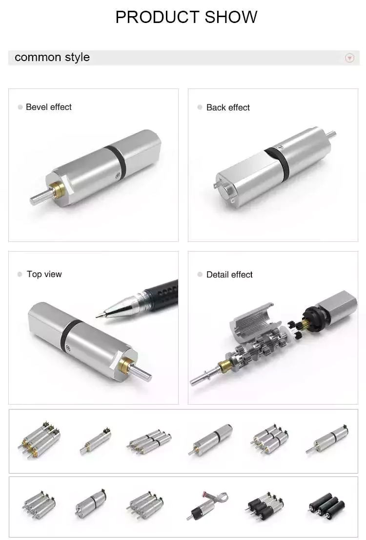
Motor

Encoder

The Mega Torque Planetary Encoder DC Geared Motor is designed with a Japanese Mabuchi motor RS-775WC, a 200 RPM base motor. It is capable of achieving stall torque at low speeds, which is impossible to achieve with a simple DC motor. The planetary encoder provides five pulses per revolution, making it perfect for applications requiring precise torque or position. This motor requires an 8mm hex coupling for proper use.
This encoder has a high resolution and is suitable for ZGX38REE, ZGX45RGG and ZGX50RHH. It features a magnetic disc and poles and an optical disc to feed back signals. It can count paulses as the motor passes through a hall on the circuit board. Depending on the gearbox ratio, the encoder can provide up to two million transitions per rotation.
The planetary gear motor uses a planetary gear system to distribute torque in synchrony. This minimizes the risk of gear failure and increases the overall output capacity of the device. On the other hand, a spur gear motor is a simpler design and cheaper to produce. The spur gear motor works better for lower torque applications as each gear bears all the load. As such, the torque capacity of the spur gear motor is lower than that of a planetary gear motor.
The REV UltraPlanetary gearbox is designed for FTC and has three different output shaft options. The output shaft is made of 3/8-inch hex, allowing for flexible shaft replacement. These motors are a great value as they can be used to meet a wide range of power requirements. The REV UltraPlanetary gearbox and motor are available for very reasonable prices and a female 5mm hex output shaft can be used.

Durability

One of the most common questions when selecting a planetary motor is “How durable is it?” This is a question that’s often asked by people. The good news is that planetary motors are extremely durable and can last for a long time if properly maintained. For more information, read on! This article will cover the durability and efficiency of planetary gearmotors and how you can choose the best one for your needs.
First and foremost, planetary gear sets are made from metal materials. This increases their lifespan. The planetary gear set is typically made of metals such as nickel-steel and steel. Some planetary gear motors use plastic. Steel-cut gears are the most durable and suitable for applications that require more torque. Nickel-steel gears are less durable, but are better able to hold lubricant.
Durability of planetary motor gearbox is important for applications requiring high torque versus speed. VEX VersaPlanetary gearboxes are designed for FRC(r) use and are incredibly durable. They are expensive, but they are highly customizable. The planetary gearbox can be removed for maintenance and replacement if necessary. Parts for the gearbox can be purchased separately. VEX VersaPlanetary gearboxes also feature a pinion clamped onto the motor shaft.
Dynamic modeling of the planetary gear transmission system is important for understanding its durability. In previous studies, uncoupled and coupled meshing models were used to investigate the effect of various design parameters on the vibration characteristics of the planetary gear system. This analysis requires considering the role of the mesh stiffness, structure stiffness, and moment of inertia. Moreover, dynamic models for planetary gear transmission require modeling the influence of multiple parameters, such as mesh stiffness and shaft location.
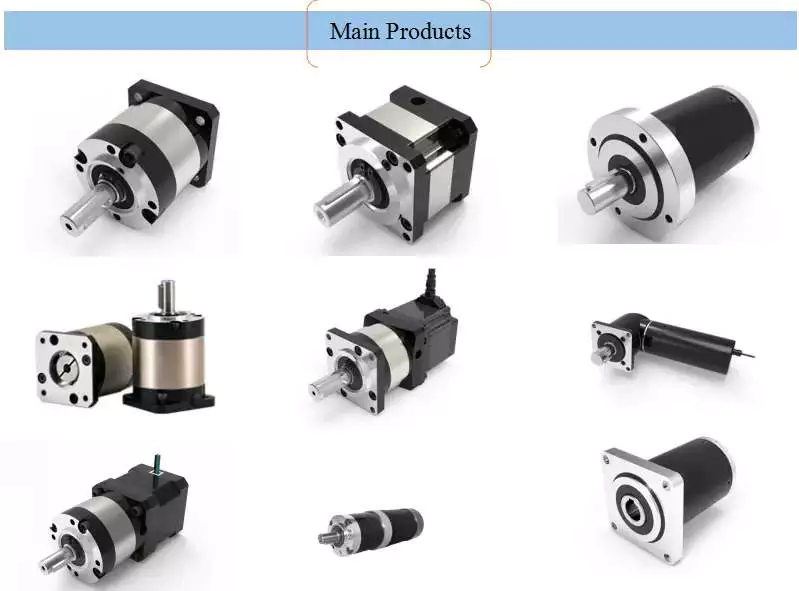
Motor

Cost

The planetary gear motor has multiple contact points that help the rotor rotate at different speeds and torques. This design is often used in stirrers and large vats of liquid. This type of motor has a low initial cost and is more commonly found in low-torque applications. A planetary gear motor has multiple contact points and is more effective for applications requiring high torque. Gear motors are often found in stirring mechanisms and conveyor belts.
A planetary gearmotor is typically made from four mechanically linked rotors. They can be used for various applications, including automotive and laboratory automation. The plastic input stage gears reduce noise at higher speeds. Steel gears can be used for high torques and a modified lubricant is often added to reduce weight and mass moment of inertia. Its low-cost design makes it an excellent choice for robots and other applications.
There are many different types of planetary gear motors available. A planetary gear motor has three gears, the sun gear and planet gears, with each sharing equal amounts of work. They are ideal for applications requiring high torque and low-resistance operation, but they require more parts than their single-stage counterparts. The steel cut gears are the most durable, and are often used in applications that require high speeds. The nickel-steel gears are more absorptive, which makes them better for holding lubricant.
A planetary gear motor is a high-performance electrical vehicle motor. A typical planetary gear motor has a 3000 rpm speed, a peak torque of 0.32 Nm, and is available in 24V, 36V, and 48V power supply. It is also quiet and efficient, requiring little maintenance and offering greater torque to a modern electric car. If you are thinking of buying a planetary gear motor, be sure to do a bit of research before purchasing one.

China ZLTECH IP54 5inch 24V 3N.m 150W brushless stainless wheel Robot AGV hub servo motor with 4095-wire encoder for support custom     supplier China ZLTECH IP54 5inch 24V 3N.m 150W brushless stainless wheel Robot AGV hub servo motor with 4095-wire encoder for support custom     supplier
editor by czh 2023-02-22

China factory Custom 1500rpm 72v 4500w harga BLDC hub motor near me supplier

Warranty: 3months-1year
Model Number: VOL-BL4K5A72
Usage: BOAT, Car, Electric Bicycle, FAN, Home Appliance, Shell Eco-marathon Competition Car
Type: brushless DC motor
Torque: 28.65Nm
Construction: Permanent Magnet
Commutation: Brushless
Protect Feature: Drip-proof
Speed(RPM): 1500RPM
Continuous Current(A): 66.49A
Efficiency: IE 4
Housing: Aluminum Frame
Speed Range: 1500rpm
Material: Permanent Magnets
Controller: Customized, Optional
Braker: Optional
Insulation Class: Class F
Enclosure: IP54
Poles: 4P, 6P, 8P, 10P…
Wire: 100% copper
Buty: S1 (continuous)
Certification: CCC, ce, RoHS
Packaging Details: short delivery time 1500RPM 72V 4500W BLDC Motor Packing: Standard sea or air package will be perfectly protected in the delivery.
Port: FOB HangZhou

Product Display

Motor type
Output Power
Voltage
Load
Speed
Rated Torque
Efficiency
Noise
IP Class

KW
V
A
RPM
Nm
%
dB

VOL-BL3K5A72
3.5
72
51.71
1500
22.28
94
62
IP 54

VOL-BL3K5A110
3.5
110 ac
19.54
1500
22.28
94
62
IP 54

VOL-BL3K5A220
3.5
220 ac
9.77
1500
22.28
94
62
IP 54

VOL-BL3K5A380
3.5
380 ac
5.66
1500
22.28
94
62
IP 54

VOL-BL3K5B72
3.5
72
51.71
3000
11.14
94
62
IP 54

VOL-BL3K5B110
3.5
110 ac
19.54
3000
11.14
94
62
IP 54

VOL-BL3K5B220
3.5
220 ac
9.77
3000
11.14
94
62
IP 54

VOL-BL3K5B380
3.5
380 ac
5.66
3000
11.14
94
62
IP 54

VIEW MORE PLS CONTACT US >>>

Other Products
Process Flow
About Us
Packing&Transport
Q:Motor has been running then fails to start,what to do?A:Likely cause: Fuse or circuit breaker is tripped.
What to do: Replace the fuse or reset the breaker.

Likely cause: Armature is shorted. Motor may make a humming noise and the circuit breaker or fuse will trip. What to do: Disassemble motor and inspect the armature for a burnt coil. Inspect the commutator for burnt bars. If this condition exists, the motor needs to be replaced.

Likely cause: The brushes may be worn down too far and no longer make contact with the commutator. What to do: Check the brushes to make sure that they are still making contact with the commutator. Contact manufacturer for brushes.

Likely cause: Controller may be defective. What to do: Verify voltage is coming out of the controller.

Q: On initial installation, motor fails to start up,what to do?A: Likely cause: Motor is incorrectly wired What to do: Verify that the motor is wired correctly.

Likely cause: No output power from controller. What to do: Measure voltage coming from the controller.

Likely cause: Motor is damaged and the armature is rubbing against the magnets. What to do: Disassemble motor and see if the armature can be realigned by reassembly. Motor may have to be replaced.

Q: Motor takes too long to accelerate,what to do?A: Likely cause: Motor controller not properly set. What to do: Adjust the acceleration trim pot of the controller.

Likely cause: Brushes are worn. What to do: Verify brush length.

Likely cause: Bearings may be defective. What to do: Inspect bearings. Noisy or rough bearings should be replaced.

Q: Motor runs in the wrong direction,what to do?A: Likely cause: Incorrect wiring What to do: Interchange the 2 motor leads.

Q: Motor runs OK but has a clicking noise,what to do?A: Likely cause: Suspect a burr on the commutator. What to do: Remove burr from commutator using a commutator stone.

Dynamic Modeling of a Planetary Motor

A planetary gear motor consists of a series of gears rotating in perfect synchrony, allowing them to deliver torque in a higher output capacity than a spur gear motor. Unlike the planetary motor, spur gear motors are simpler to build and cost less, but they are better for applications requiring lower torque output. That is because each gear carries the entire load. The following are some key differences between the two types of gearmotors.

planetary gear system

A planetary gear transmission is a type of gear mechanism that transfers torque from one source to another, usually a rotary motion. Moreover, this type of gear transmission requires dynamic modeling to investigate its durability and reliability. Previous studies included both uncoupled and coupled meshing models for the analysis of planetary gear transmission. The combined model considers both the shaft structural stiffness and the bearing support stiffness. In some applications, the flexible planetary gear may affect the dynamic response of the system.
In a planetary gear device, the axial end surface of the cylindrical portion is rotatable relative to the separating plate. This mechanism retains lubricant. It is also capable of preventing foreign particles from entering the planetary gear system. A planetary gear device is a great choice if your planetary motor’s speed is high. A high-quality planetary gear system can provide a superior performance than conventional systems.
A planetary gear system is a complex mechanism, involving three moving links that are connected to each other through joints. The sun gear acts as an input and the planet gears act as outputs. They rotate about their axes at a ratio determined by the number of teeth on each gear. The sun gear has 24 teeth, while the planet gears have three-quarters that ratio. This ratio makes a planetary motor extremely efficient.
Motor

planetary gear train

To predict the free vibration response of a planetary motor gear train, it is essential to develop a mathematical model for the system. Previously, static and dynamic models were used to study the behavior of planetary motor gear trains. In this study, a dynamic model was developed to investigate the effects of key design parameters on the vibratory response. Key parameters for planetary gear transmissions include the structure stiffness and mesh stiffness, and the mass and location of the shaft and bearing supports.
The design of the planetary motor gear train consists of several stages that can run with variable input speeds. The design of the gear train enables the transmission of high torques by dividing the load across multiple planetary gears. In addition, the planetary gear train has multiple teeth which mesh simultaneously in operation. This design also allows for higher efficiency and transmittable torque. Here are some other advantages of planetary motor gear trains. All these advantages make planetary motor gear trains one of the most popular types of planetary motors.
The compact footprint of planetary gears allows for excellent heat dissipation. High speeds and sustained performances will require lubrication. This lubricant can also reduce noise and vibration. But if these characteristics are not desirable for your application, you can choose a different gear type. Alternatively, if you want to maintain high performance, a planetary motor gear train will be the best choice. So, what are the advantages of planetary motor gears?

planetary gear train with fixed carrier train ratio

The planetary gear train is a common type of transmission in various machines. Its main advantages are high efficiency, compactness, large transmission ratio, and power-to-weight ratio. This type of gear train is a combination of spur gears, single-helical gears, and herringbone gears. Herringbone planetary gears have lower axial force and high load carrying capacity. Herringbone planetary gears are commonly used in heavy machinery and transmissions of large vehicles.
To use a planetary gear train with a fixed carrier train ratio, the first and second planets must be in a carrier position. The first planet is rotated so that its teeth mesh with the sun’s. The second planet, however, cannot rotate. It must be in a carrier position so that it can mesh with the sun. This requires a high degree of precision, so the planetary gear train is usually made of multiple sets. A little analysis will simplify this design.
The planetary gear train is made up of three components. The outer ring gear is supported by a ring gear. Each gear is positioned at a specific angle relative to one another. This allows the gears to rotate at a fixed rate while transferring the motion. This design is also popular in bicycles and other small vehicles. If the planetary gear train has several stages, multiple ring gears may be shared. A stationary ring gear is also used in pencil sharpener mechanisms. Planet gears are extended into cylindrical cutters. The ring gear is stationary and the planet gears rotate around a sun axis. In the case of this design, the outer ring gear will have a -3/2 planet gear ratio.
Motor

planetary gear train with zero helix angle

The torque distribution in a planetary gear is skewed, and this will drastically reduce the load carrying capacity of a needle bearing, and therefore the life of the bearing. To better understand how this can affect a gear train, we will examine two studies conducted on the load distribution of a planetary gear with a zero helix angle. The first study was done with a highly specialized program from the bearing manufacturer INA/FAG. The red line represents the load distribution along a needle roller in a zero helix gear, while the green line corresponds to the same distribution of loads in a 15 degree helix angle gear.
Another method for determining a gear’s helix angle is to consider the ratio of the sun and planet gears. While the sun gear is normally on the input side, the planet gears are on the output side. The sun gear is stationary. The two gears are in engagement with a ring gear that rotates 45 degrees clockwise. Both gears are attached to pins that support the planet gears. In the figure below, you can see the tangential and axial gear mesh forces on a planetary gear train.
Another method used for calculating power loss in a planetary gear train is the use of an auto transmission. This type of gear provides balanced performance in both power efficiency and load capacity. Despite the complexities, this method provides a more accurate analysis of how the helix angle affects power loss in a planetary gear train. If you’re interested in reducing the power loss of a planetary gear train, read on!

planetary gear train with spur gears

A planetary gearset is a type of mechanical drive system that uses spur gears that move in opposite directions within a plane. Spur gears are one of the more basic types of gears, as they don’t require any specialty cuts or angles to work. Instead, spur gears use a complex tooth shape to determine where the teeth will make contact. This in turn, will determine the amount of power, torque, and speed they can produce.
A two-stage planetary gear train with spur gears is also possible to run at variable input speeds. For such a setup, a mathematical model of the gear train is developed. Simulation of the dynamic behaviour highlights the non-stationary effects, and the results are in good agreement with the experimental data. As the ratio of spur gears to spur gears is not constant, it is called a dedendum.
A planetary gear train with spur gears is a type of epicyclic gear train. In this case, spur gears run between gears that contain both internal and external teeth. The circumferential motion of the spur gears is analogous to the rotation of planets in the solar system. There are four main components of a planetary gear train. The planet gear is positioned inside the sun gear and rotates to transfer motion to the sun gear. The planet gears are mounted on a joint carrier that is connected to the output shaft.
Motor

planetary gear train with helical gears

A planetary gear train with helical teeth is an extremely powerful transmission system that can provide high levels of power density. Helical gears are used to increase efficiency by providing a more efficient alternative to conventional worm gears. This type of transmission has the potential to improve the overall performance of a system, and its benefits extend far beyond the power density. But what makes this transmission system so appealing? What are the key factors to consider when designing this type of transmission system?
The most basic planetary train consists of the sun gear, planet gear, and ring gear elements. The number of planets varies, but the basic structure of planetary gears is similar. A simple planetary geartrain has the sun gear driving a carrier assembly. The number of planets can be as low as two or as high as six. A planetary gear train has a low mass inertia and is compact and reliable.
The mesh phase properties of a planetary gear train are particularly important in designing the profiles. Various parameters such as mesh phase difference and tooth profile modifications must be studied in depth in order to fully understand the dynamic characteristics of a PGT. These factors, together with others, determine the helical gears’ performance. It is therefore essential to understand the mesh phase of a planetary gear train to design it effectively.

China factory Custom 1500rpm 72v 4500w harga BLDC hub motor  near me supplier China factory Custom 1500rpm 72v 4500w harga BLDC hub motor  near me supplier

China Best Sales CE certified 6.5 inch high torque 6.5 N.m low rpm 200 RPM dc automated guided vehicle agv brushless gearless hub servo motor with high quality

Warranty: 3months-1year
Model Number: ZLLG65ASM250-L
Usage: Robot, AGV
Type: SERVO MOTOR
Torque: 6.5N.M
Construction: Permanent Magnet
Commutation: Brushless
Protect Feature: Drip-proof
Speed(RPM): 200RPM
Continuous Current(A): 3-17A
Efficiency: Ie 3
Certification: ce
Outside diameter with tyre: 170mm
Shaft type: single/double shaft
Power type: DC motor
Rated voltage: 24VDC
Rated torque: 6.5N.M
Rated power: 150W
Rated current: 3-17A
Rated speed: 200RPM
Packaging Details: Wrapped with plastic bags and embedded in the foam;Carton size: 26×21.5×22.5cm; QTY: 2pcs per carton;Carton Weight: 6.3kg/2pcs

CE certified 6.5 inch high torque 6.5 N.m low rpm 200 RPM dc automated guided vehicle agv brushless gearless hub servo motor
Parameters:

Outside Diameter
6.5 inch
Voltage
24V
Encoder
1571 line Incremental Photoelectric Encoder
Efficiency
≥85%
Power type
DC motor
Carrying weight
≤150KG
Shaft connection
thread
Brake method
electric brake
Excitation mode
permanent magnet type
Tyre form
with pattern
Matching driver
ZLAC706/ZLAC706-CAN/ZLAC706-RC
Environment temperature
-10 ~ +40 degree centigrade

Our hub servo motor advantage:

  • Self R & D, have own patent and great market competitiveness
  • Built-in high precision encoder 12-21 bits optional, also can be customized, electric brake, high load carrying etc
  • Simple structure, easy installation and high cost performance
  • High precision, high power density, low noise, efficient and durable
  • The motor and the outer tyre are integrated, beautiful design
  • 4-15 inch optional, power: 50-2KW optional, accept OEM/OEM for all models
  • More robot motor pictures:

    Incremental Photoelectric encoder:
    Dimension of the servo hub motor double shaft:

    Dimension of the single shaft:
    More Robot AGV dc hub servo motor:

    Application: service Robot, AGV car

    Bulk production

    Patent for the servo hub motor:

    Packaging & ShippingPackage: carton with foam, quantity per carton will depend on the hub motor size.
    Shipping: goods will be deliveried by air(EMS, DHL, FedEx,TNT etc), by train or by boat according to your requirements.

    Company Information1. Brief introduction:
    HangZhou CZPT Technology Co., Ltd. is a high-tech enterprise specialized in R&D, production and sales of industrial automation transmission products; The company gathered a large number of R&D elites being engaged in motion control field for more than 10 years and constantly provide cost-effective motion control products for our partners.
    2. Product ranges and application:
    Robot Hub Servo Motor, Digital Stepper Driver, Closed Loop Stepper Driver, Low-voltage DC Servo Driver and Stepper Motor, Multi-axis Motion Controller etc.. And widely used in hundreds of industries like Electronics, Machinery, Measurement, Laser, Medical, Textile, Packaging, LDE equipment, Channel CZPT and Advertising etc.. Our products has win great popularity in global and been exported to global market like Southeast Asia, Europe and the United States etc.
    3. Our service philosophy: Create value for customers.
    4. Core value: Dedicated, innovative, virtuous, and pragmatic
    5. Our vision: Being the most professional brand in the field of automation control, serving the global industry

    About CZPT products on Exhibition:

    Contact: Tel: -571-29799302; Cel: -18118726452;
    FAQ 1. Factory or trader?We are factory, and have professional R&D team as introduced in company information.
    2. How about the delivery?– Sample: 3-5 days.- Bulk order: 15-30 days.

    3. What is your after-sales services?1. Free maintenance within 12 months guarantee, lifetime consultant.2. Professional solutions in installation and maintence.
    4. Why choose us?1. Factory Price & 24/7 after-sale services.2. From mold customization to material processing and welding, from fine components to finished assembly, 72 processes, 24 control points, strict aging, finished product inspection.

    How to Maximize Gear Motor Reliability

    A gearmotor is a mechanical device used to transmit torque from one location to another. As its name implies, it is designed to rotate one object relative to another. Its main use is to transmit torque from one point to another. The most common types of gear motors are: worm, spur, and helical. Each of these has specific functions and can be used for a variety of applications. Reliability is also an important factor to consider when choosing a gearmotor.

    Applications of a gear motor

    Despite its small size, a gear motor has many applications. These include heavy machinery lifts, hospital beds, and power recliners. It is also found in many everyday products, such as electromechanical clocks and cake mixers. Its versatility allows it to produce a high force from a small electric motor. Here are some of its most common uses. You can also find a gear motor in many household appliances and vehicles.
    Before selecting a gearmotor, consider the specifications of the machine you need to power. You should consider its size, weight, and ambient conditions, which include temperature regimes, noise levels, and contaminating sources. You should also take into account the envelope size, mounting method, and orientation. Other considerations include the expected service life, maintenance scope, and control type. The most suitable gearmotor for your specific application will be one that can handle the load.
    The motor and gearbox types can be mixed and matched, depending on the application. A three-phase asynchronous motor and a permanent magnet synchronous servomotor are common choices for these devices. The type of motor and gearbox combination you choose will determine the power supply, the efficiency of the motor, and cost. Once you understand the application, it will be easy to integrate a gear motor into your system.
    When used in industrial applications, gear motors are effective for reducing the speed of rotating shafts. One third of all industrial electric motor systems use gearing to reduce output speed. They can also save energy, which benefits the workers who operate them. In fact, industrial electric motor systems are responsible for nearly one-tenth of the carbon dioxide emissions that are produced by fossil-fueled power plants. Fortunately, efficiency and reliability are just two of the benefits of using gear motors.
    Motor

    Types

    Before choosing a gearmotor, it is important to understand its specifications. The key factors to consider are the size, weight, and noise level of the gearmotor. Additionally, the power, torque, and speed of the motor are important factors. Specifications are also important for its operating environment, such as the temperature and the level of ingress protection. Finally, it is important to determine its duty cycle to ensure it will operate properly. To choose a suitable gearmotor, consult the specifications of your application.
    Some common applications of gearmotors include packaging equipment, conveyors, and material handling applications. They also come with several advantages, including their ability to control both position and speed. This makes them ideal for applications where speed and positioning are crucial. Parallel-shaft gear units, for instance, are commonly used in conveyors, material handling, and steel mills. They are also able to operate in high-precision manufacturing. For these reasons, they are the most popular type of gearmotor.
    There are three common types of gears. Helical gears have teeth that are inclined at 90 degrees to the axis of rotation, making them more efficient. Helicoidal gears, meanwhile, have a lower noise level and are therefore preferred for applications requiring high torque. Worm gears are preferred for applications where torque and speed reduction are important, and worm gears are suited for those conditions. They also have advantages over spur gears and worm gears.
    The application of a gear motor is almost limitless. From heavy machine lifts to hospital bed lifting mechanisms, gear motors make it possible to use a small rotor at a high speed. Their lightweight construction also allows them to move heavy loads, such as cranes, but they do so slowly. Gear motors are an excellent choice in applications where space is an issue. A few common applications are discussed below. When choosing a gear motor, remember to choose the best size and application for your needs.
    Motor

    Functions

    A gearmotor’s speed is directly proportional to the gear ratio. By dividing the input speed by the gear ratio, the output speed can be determined. Gear ratios above one reduce speed, while gear ratios below one increase speed. Efficiency of a gearmotor is defined as its ability to transfer energy through its gearbox. This efficiency factor takes into account losses from friction and slippage. Most gearmotor manufacturers will provide this curve upon request.
    There are several factors that must be considered when choosing a gearmotor. First, the application must meet the desired speed and torque. Second, the output shaft must rotate in the desired direction. Third, the load must be properly matched to the gearmotor. Lastly, the operating environment must be considered, including the ambient temperature and the level of protection. These details will help you find the perfect gearmotor. You can compare various types of gear motors on this page and choose the one that will meet your needs.
    The micro-DC gear motor is one of the most versatile types of geared motors. These motors are widely used in intelligent automobiles, robotics, logistics, and the smart city. Other applications include precision instruments, personal care tools, and cameras. They are also commonly found in high-end automotives and are used in smart cities. They also find use in many fields including outdoor adventure equipment, photography equipment, and electronics. The benefits of micro-DC gear motors are many.
    The main function of a gear motor is to reduce the speed of a rotating shaft. Small electric clocks, for example, use a synchronous motor with a 1,200-rpm output speed to drive the hour, minute, and second hands. While the motor is small, the force it exerts is enormous, so it’s crucial to ensure that the motor isn’t over-powered. There is a high ratio between the input torque and the output torque.

    Reliability

    The reliability of a gear motor is dependent on a number of factors, including material quality, machining accuracy, and operating conditions. Gear failure is often more serious than surface fatigue, and can compromise personal safety. Reliability is also affected by the conditions of installation, assembly, and usage. The following sections provide an overview of some important factors that impact gear motor reliability. This article provides some tips to maximize gear motor reliability.
    First and foremost, make sure you’re buying from a reliable supplier. Gear motors are expensive, and there is no standardization of the sizes. If a gear breaks, replacing it can take a lot of time. In the long run, reliability wins over anything. But this doesn’t mean that you can ignore the importance of gears – the quality of a gear motor is more important than how long it lasts.
    Motor

    Cost

    The cost of a gear motor is relatively low compared to that of other forms of electric motors. This type of motor is commonly used in money counters, printers, smart homes, and automation equipment. A DC gear motor is also commonly used in automatic window machines, glass curtain walls, and banknote vending machines. There are many advantages to using a gear motor. Here are a few of them. Read on to learn more about them.
    Speed management is another benefit of a gear motor. The motors tend to have less wear and tear than other motors, which means less frequent replacements. Additionally, many gear motors are easy to install and require less maintenance, which also helps reduce the overall cost of ownership. Lastly, because noise is a common concern for many electronic OEMs, DC gear motors are often quieter than their counterparts. For these reasons, they are often used in industrial settings.
    Another advantage of an electric gear motor is its size and power. They are typically designed for 12V, 24V, and 48V voltages and 200-watt power. Their rated speed is 3000 rpm and their torque is 0.64 Nm. They are also more reliable than their AC counterparts and are ideal for many industrial applications. They have a high ratio of three to two, which makes them ideal for a variety of applications.
    A gear motor is an electric motor that is coupled with a gear train. It uses AC or DC power, and is often called a gear reducer. The main purpose of these gear reducers is to multiply torque, while maintaining compact size and overall efficiency. However, the efficiency of a gear motor is also affected by ambient temperature and lubricants. If the gear motor is installed in the wrong location, it may be ineffective and result in premature failure of the machine.

    China Best Sales CE certified 6.5 inch high torque 6.5 N.m low rpm 200 RPM dc automated guided vehicle agv brushless gearless hub servo motor  with high qualityChina Best Sales CE certified 6.5 inch high torque 6.5 N.m low rpm 200 RPM dc automated guided vehicle agv brushless gearless hub servo motor  with high quality