Product Description
Product Description
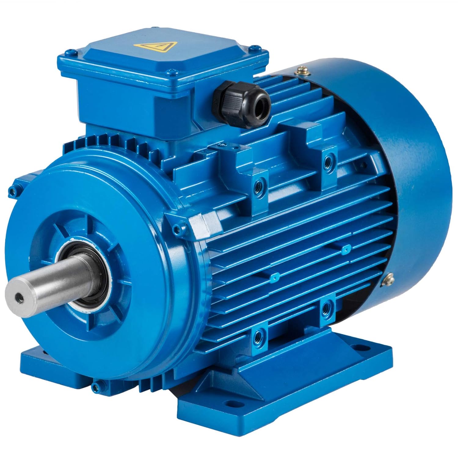
Elevator Geared Traction Machine
General Information for the Elevator Motor
1. Type: VVVF asynchronous and geared
2. Traction Sheave Location: Optional for right or left
3. Load: 2000KG to 2500KG
4. Speed: 0.5m/s to 2.0m/s
5. Application: For new elevator or elevator modernization
Features for Geared VVVF Asynchronous Elevator Traction Machine
1. High efficiency
2. Stable and low noise
3. High static load capacity
|
Model |
NV41G |
|
Speed(m/s) |
0.5 – 2 |
|
Weight |
730kg |
|
Suspension |
1:1 |
|
Max.Static Load |
7500kg |
|
Control |
VVVF |
|
Brake |
DC110V 2A |
Product Parameters
|
Model |
Load |
Lift Speed |
Ratio |
Sheave Diam |
Rope Sheave |
Motor Power |
Pole |
|
NV41G |
800 |
1.6 |
59:2 |
Φ620 |
5×Φ13×20 |
12.5 |
4 |
|
NV41G |
800 |
1.75 |
55:2 |
Φ620 |
5×Φ13×20 |
15 |
4 |
|
NV41G |
800 |
2 |
49:2 |
Φ620 |
6×Φ13×20 |
18.5 |
4 |
|
NV41G |
1000 |
1 |
49:1 |
Φ620 |
5×Φ13×20 |
11 |
4 |
|
NV41G |
1000 |
1.6 |
59:2 |
Φ620 |
6×Φ13×20 |
18.5 |
4 |
|
NV41G |
1000 |
1.75 |
55:2 |
Φ620 |
6×Φ13×20 |
18.5 |
4 |
|
NV41G |
1000 |
2 |
49:2 |
Φ620 |
6×Φ13×20 |
18.5 |
4 |
|
NV41G |
1150 |
1 |
49:1 |
Φ620 |
6×Φ13×20 |
15 |
4 |
|
NV41G |
1150 |
1.6 |
59:2 |
Φ620 |
6×Φ13×20 |
18.5 |
4 |
|
NV41G |
1150 |
1.75 |
55:2 |
Φ620 |
6×Φ13×20 |
18.5 |
4 |
|
NV41G |
1150 |
2 |
49:2 |
Φ620 |
6×Φ13×20 |
22 |
4 |
Different Models
The worm geared asynchronous traction machine is combined by coupling to integrate worm reduction gearbox and 3 phase synchronous motor, with underlying worm, double push brake, dual support-stuctured traction sheave, VVVF controlled asynchronous motor and photoelectric encoder for operation status detecting and feedback.
Main Product Catalog
Company Profile
Exhibition
Packaging & Shipping
Why Choose Us
/* January 22, 2571 19:08:37 */!function(){function s(e,r){var a,o={};try{e&&e.split(“,”).forEach(function(e,t){e&&(a=e.match(/(.*?):(.*)$/))&&1
| After-sales Service: | Online |
|---|---|
| Warranty: | 24 Months |
| Type: | Elevator Traction Machine |
| Suitable for: | Elevator |
| Load Capacity: | 2000kg |
| Persons: | 11-20 |
| Customization: |
Available
|
|
|---|

Can AC motors be used in both residential and commercial settings?
Yes, AC motors can be used in both residential and commercial settings. The versatility and wide range of applications of AC motors make them suitable for various environments and purposes.
In residential settings, AC motors are commonly found in household appliances such as refrigerators, air conditioners, washing machines, fans, and pumps. These motors are designed to meet the specific requirements of residential applications, providing reliable and efficient operation for everyday tasks. For example, air conditioners utilize AC motors to drive the compressor and fan, while washing machines use AC motors for agitating and spinning the drum.
In commercial settings, AC motors are extensively used in a wide range of applications across different industries. They power machinery, equipment, and systems that are crucial for commercial operations. Some common examples include:
- Industrial machinery and manufacturing equipment: AC motors drive conveyor belts, pumps, compressors, mixers, fans, blowers, and other machinery used in manufacturing, production, and processing facilities.
- HVAC systems: AC motors are used in commercial heating, ventilation, and air conditioning (HVAC) systems to drive fans, blowers, and pumps for air circulation, cooling, and heating.
- Commercial refrigeration: AC motors are utilized in commercial refrigeration systems for powering compressors, condenser fans, and evaporator fans in supermarkets, restaurants, and cold storage facilities.
- Office equipment: AC motors are present in various office equipment such as printers, photocopiers, scanners, and ventilation systems, ensuring their proper functioning.
- Transportation: AC motors are used in electric vehicles, trams, trains, and other forms of electric transportation systems, providing the necessary propulsion.
- Water and wastewater treatment: AC motors power pumps, mixers, and blowers in water treatment plants, wastewater treatment plants, and pumping stations.
The adaptability, efficiency, and controllability of AC motors make them suitable for a wide range of residential and commercial applications. Whether it’s powering household appliances or driving industrial machinery, AC motors play a vital role in meeting the diverse needs of both residential and commercial settings.

Can AC motors be used in renewable energy systems, such as wind turbines?
Yes, AC motors can be used in renewable energy systems, including wind turbines. In fact, AC motors are commonly employed in various applications within wind turbines due to their numerous advantages. Here’s a detailed explanation:
1. Generator: In a wind turbine system, the AC motor often functions as a generator. As the wind turbine blades rotate, they drive the rotor of the generator, which converts the mechanical energy of the wind into electrical energy. AC generators are commonly used in wind turbines due to their efficiency, reliability, and compatibility with power grid systems.
2. Variable Speed Control: AC motors offer the advantage of variable speed control, which is crucial for wind turbines. The wind speed is variable, and in order to maximize energy capture, the rotor speed needs to be adjusted accordingly. AC motors, when used as generators, can adjust their rotational speed with the changing wind conditions by modifying the frequency and voltage of the output electrical signal.
3. Efficiency: AC motors are known for their high efficiency, which is an important factor in renewable energy systems. Wind turbines aim to convert as much of the wind energy into electrical energy as possible. AC motors, especially those designed for high efficiency, can help maximize the overall energy conversion efficiency of the wind turbine system.
4. Grid Integration: AC motors are well-suited for grid integration in renewable energy systems. The electrical output from the AC generator can be easily synchronized with the grid frequency and voltage, allowing for seamless integration of the wind turbine system with the existing power grid infrastructure. This facilitates the efficient distribution of the generated electricity to consumers.
5. Control and Monitoring: AC motors offer advanced control and monitoring capabilities, which are essential for wind turbine systems. The electrical parameters, such as voltage, frequency, and power output, can be easily monitored and controlled in AC motor-based generators. This allows for real-time monitoring of the wind turbine performance, fault detection, and optimization of the power generation process.
6. Availability and Standardization: AC motors are widely available in various sizes and power ratings, making them readily accessible for wind turbine applications. They are also well-standardized, ensuring compatibility with other system components and facilitating maintenance, repair, and replacement activities.
It’s worth noting that while AC motors are commonly used in wind turbines, there are other types of generators and motor technologies utilized in specific wind turbine designs, such as permanent magnet synchronous generators (PMSGs) or doubly-fed induction generators (DFIGs). These alternatives offer their own advantages and may be preferred in certain wind turbine configurations.
In summary, AC motors can indeed be used in renewable energy systems, including wind turbines. Their efficiency, variable speed control, grid integration capabilities, and advanced control features make them a suitable choice for converting wind energy into electrical energy in a reliable and efficient manner.

What is an AC motor, and how does it differ from a DC motor?
An AC motor, also known as an alternating current motor, is a type of electric motor that operates on alternating current. It converts electrical energy into mechanical energy through the interaction of magnetic fields. AC motors are widely used in various applications, ranging from household appliances to industrial machinery. Here’s a detailed explanation of what an AC motor is and how it differs from a DC motor:
AC Motor:
An AC motor consists of two main components: the stator and the rotor. The stator is the stationary part of the motor and contains the stator windings. These windings are typically made of copper wire and are arranged in specific configurations to create a rotating magnetic field when energized by an alternating current. The rotor, on the other hand, is the rotating part of the motor and is typically made of laminated steel cores with conducting bars or coils. The rotor windings are connected to a shaft, and their interaction with the rotating magnetic field produced by the stator causes the rotor to rotate.
The operation of an AC motor is based on the principles of electromagnetic induction. When the stator windings are energized with an AC power supply, the changing magnetic field induces a voltage in the rotor windings, which in turn creates a magnetic field. The interaction between the rotating magnetic field of the stator and the magnetic field of the rotor produces a torque, causing the rotor to rotate. The speed of rotation depends on the frequency of the AC power supply and the number of poles in the motor.
DC Motor:
A DC motor, also known as a direct current motor, operates on direct current. Unlike an AC motor, which relies on the interaction of magnetic fields to generate torque, a DC motor uses the principle of commutation to produce rotational motion. A DC motor consists of a stator and a rotor, similar to an AC motor. The stator contains the stator windings, while the rotor consists of a rotating armature with coils or permanent magnets.
In a DC motor, when a direct current is applied to the stator windings, a magnetic field is created. The rotor, either through the use of brushes and a commutator or electronic commutation, aligns itself with the magnetic field and begins to rotate. The direction of the current in the rotor windings is continuously reversed to ensure continuous rotation. The speed of a DC motor can be controlled by adjusting the voltage applied to the motor or by using electronic speed control methods.
Differences:
The main differences between AC motors and DC motors are as follows:
- Power Source: AC motors operate on alternating current, which is the standard power supply in most residential and commercial buildings. DC motors, on the other hand, require direct current and typically require a power supply that converts AC to DC.
- Construction: AC motors and DC motors have similar construction with stators and rotors, but the design and arrangement of the windings differ. AC motors generally have three-phase windings, while DC motors can have either armature windings or permanent magnets.
- Speed Control: AC motors typically operate at fixed speeds determined by the frequency of the power supply and the number of poles. DC motors, on the other hand, offer more flexibility in speed control and can be easily adjusted over a wide range of speeds.
- Efficiency: AC motors are generally more efficient than DC motors. AC motors can achieve higher power densities and are often more suitable for high-power applications. DC motors, however, offer better speed control and are commonly used in applications that require precise speed regulation.
- Applications: AC motors are widely used in applications such as industrial machinery, HVAC systems, pumps, and compressors. DC motors find applications in robotics, electric vehicles, computer disk drives, and small appliances.
In conclusion, AC motors and DC motors differ in their power source, construction, speed control, efficiency, and applications. AC motors rely on the interaction of magnetic fields and operate on alternating current, while DC motors use commutation and operate on direct current. Each type of motor has its advantages and is suited for different applications based on factors such as power requirements, speed control needs, and efficiency considerations.


editor by CX 2024-04-17
China Custom CHINAMFG Pmsm AC 3 Phase Electrical Permanent Magnet 20kw Pmsm Synchonous Motor vacuum pump ac system
Product Description
Product Description
Δ Kindly remind: As different customers may need different motor parameter for fitting your equipment. If below motor can’t fit your need, please kindly send inquiry to us with information for rated power or torque,rated speed, and rated voltage for our new size drawing making for you. CLICK HERE to contact me. Thanks a lot!
Dimensions (Unit: mm )
DMK25-270F172R AC Permanent Magnet Synchronous Motor Specification:
For More Details Of Product Specifications,
Please Click here contact us for updated size drawing if you have other different parameter needed. Thanks
More Motor To Choose
Δ Welcome to contact us to custom.
BLDC Motor with Gearbox Range
Company Profile
DMKE motor was founded in China, HangZhou city,Xihu (West Lake) Dis. district, in 2009. After 12 years’ creativity and development, we became 1 of the leading high-tech companies in China in dc motor industry.
We specialize in high precision micro dc gear motors, brushless motors, brushless controllers, dc servo motors, dc servo controllers etc. And we produce brushless dc motor and controller with wide power range from 5 watt to 20 kilowatt; also dc servo motor power range from 50 watt to 10 kilowatt. They are widely used in automatic guided vehicle , robots, lifting equipment,cleaning machine, medical equipment, packing machinery, and many other industrial automatic equipments.
With a plant area of 4000 square meters, we have built our own supply chain with high quality control standard and passed ISO9001 certificate of quality system.
With more than 10 engineers for brushless dc motor and controllers’ research and development, we own strong independent design and development capability. Custom-made motors and controllers are widely accepted by us. At the same time, we have engineers who can speak fluent English. That makes we can supply intime after-sales support and guidance smoothly for our customers.
Our motors are exported worldwide, and over 80% motors are exported to Europe, the United States, Saudi Arabia, Australia, Korea etc. We are looking CHINAMFG to establishing long-term business relationship together with you for mutual business success.
FAQ
Q1: What kind motors you can provide?
A1: For now, we mainly provide permanent magnet brushless dc motor, dc gear motor, micro dc motor, planetary gear motor, dc servo motor, brush dc motors, with diameter range from 16 to 220mm,and power range from 5W to 20KW.
Q2: Is there a MOQ for your motors?
A2: No. we can accept 1 pcs for sample making for your testing,and the price for sample making will have 10% to 30% difference than bulk price based on different style.
Q3: Could you send me a price list?
A3: For all of our motors, they are customized based on different requirements like power, voltage, gear ratio, rated torque and shaft diameter etc. The price also varies according to different order qty. So it’s difficult for us to provide a price list.
If you can share your detailed specification and order qty, we’ll see what offer we can provide.
Q4: Are you motors reversible?
A4: Yes, nearly all dc and ac motor are reversible. We have technical people who can teach how to get the function by different wire connection.
Q5: Is it possible for you to develop new motors if we provide the tooling cost?
A5: Yes. Please kindly share the detailed requirements like performance, size, annual quantity, target price etc. Then we’ll make our evaluation to see if we can arrange or not.
Q6:How about your delivery time?
A6: For micro brush dc gear motor, the sample delivery time is 2-5 days, bulk delivery time is about 15-20 days, depends on the order qty.
For brushless dc motor, the sample deliver time is about 10-15 days; bulk time is 15-20 days.
Pleasecontact us for final reference.
Q7:What’s your warranty terms?
A6: One year
/* January 22, 2571 19:08:37 */!function(){function s(e,r){var a,o={};try{e&&e.split(“,”).forEach(function(e,t){e&&(a=e.match(/(.*?):(.*)$/))&&1
| Application: | Universal, Household Appliances, Industrial, Power Tools, Pump |
|---|---|
| Operating Speed: | Adjust Speed |
| Operation Mode: | Electric Motor |
| Magnetic Structure: | Permanent Magnet |
| Function: | Driving, Control |
| Number of Poles: | 4 |
| Samples: |
US$ 2417.8/Piece
1 Piece(Min.Order) | |
|---|
| Customization: |
Available
|
|
|---|

Can you explain the concept of motor efficiency and how it relates to AC motors?
Motor efficiency is a measure of how effectively an electric motor converts electrical power into mechanical power. It represents the ratio of the motor’s useful output power (mechanical power) to the input power (electrical power) it consumes. Higher efficiency indicates that the motor converts a larger percentage of the electrical energy into useful mechanical work, while minimizing energy losses in the form of heat and other inefficiencies.
In the case of AC motors, efficiency is particularly important due to their wide usage in various applications, ranging from residential appliances to industrial machinery. AC motors can be both induction motors, which are the most common type, and synchronous motors, which operate at a constant speed synchronized with the frequency of the power supply.
The efficiency of an AC motor is influenced by several factors:
- Motor Design: The design of the motor, including its core materials, winding configuration, and rotor construction, affects its efficiency. Motors that are designed with low-resistance windings, high-quality magnetic materials, and optimized rotor designs tend to have higher efficiency.
- Motor Size: The physical size of the motor can also impact its efficiency. Larger motors generally have higher efficiency because they can dissipate heat more effectively, reducing losses. However, it’s important to select a motor size that matches the application requirements to avoid operating the motor at low efficiency due to underloading.
- Operating Conditions: The operating conditions, such as load demand, speed, and temperature, can influence motor efficiency. Motors are typically designed for maximum efficiency at or near their rated load. Operating the motor beyond its rated load or at very light loads can reduce efficiency. Additionally, high ambient temperatures can cause increased losses and reduced efficiency.
- Magnetic Losses: AC motors experience losses due to magnetic effects, such as hysteresis and eddy current losses in the core materials. These losses result in heat generation and reduce overall efficiency. Motor designs that minimize magnetic losses through the use of high-quality magnetic materials and optimized core designs can improve efficiency.
- Mechanical Friction and Windage Losses: Friction and windage losses in the motor’s bearings, shaft, and rotating parts also contribute to energy losses and reduced efficiency. Proper lubrication, bearing selection, and reducing unnecessary mechanical resistance can help minimize these losses.
Efficiency is an important consideration when selecting an AC motor, as it directly impacts energy consumption and operating costs. Motors with higher efficiency consume less electrical power, resulting in reduced energy bills and a smaller environmental footprint. Additionally, higher efficiency often translates to less heat generation, which can enhance the motor’s reliability and lifespan.
Regulatory bodies and standards organizations, such as the International Electrotechnical Commission (IEC) and the National Electrical Manufacturers Association (NEMA), provide efficiency classes and standards for AC motors, such as IE efficiency classes and NEMA premium efficiency standards. These standards help consumers compare the efficiency levels of different motors and make informed choices to optimize energy efficiency.
In summary, motor efficiency is a measure of how effectively an AC motor converts electrical power into mechanical power. By selecting motors with higher efficiency, users can reduce energy consumption, operating costs, and environmental impact while ensuring reliable and sustainable motor performance.
What are the safety considerations when working with or around AC motors?
Working with or around AC motors requires careful attention to safety to prevent accidents, injuries, and electrical hazards. Here are some important safety considerations to keep in mind:
- Electrical Hazards: AC motors operate on high voltage electrical systems, which pose a significant electrical hazard. It is essential to follow proper lockout/tagout procedures when working on motors to ensure that they are de-energized and cannot accidentally start up. Only qualified personnel should perform electrical work on motors, and they should use appropriate personal protective equipment (PPE), such as insulated gloves, safety glasses, and arc flash protection, to protect themselves from electrical shocks and arc flash incidents.
- Mechanical Hazards: AC motors often drive mechanical equipment, such as pumps, fans, or conveyors, which can present mechanical hazards. When working on or near motors, it is crucial to be aware of rotating parts, belts, pulleys, or couplings that can cause entanglement or crushing injuries. Guards and safety barriers should be in place to prevent accidental contact with moving parts, and proper machine guarding principles should be followed. Lockout/tagout procedures should also be applied to the associated mechanical equipment to ensure it is safely de-energized during maintenance or repair.
- Fire and Thermal Hazards: AC motors can generate heat during operation, and in some cases, excessive heat can pose a fire hazard. It is important to ensure that motors are adequately ventilated to dissipate heat and prevent overheating. Motor enclosures and cooling systems should be inspected regularly to ensure proper functioning. Additionally, combustible materials should be kept away from motors to reduce the risk of fire. If a motor shows signs of overheating or emits a burning smell, it should be immediately shut down and inspected by a qualified professional.
- Proper Installation and Grounding: AC motors should be installed and grounded correctly to ensure electrical safety. Motors should be installed according to manufacturer guidelines, including proper alignment, mounting, and connection of electrical cables. Adequate grounding is essential to prevent electrical shocks and ensure the safe dissipation of fault currents. Grounding conductors, such as grounding rods or grounding straps, should be properly installed and regularly inspected to maintain their integrity.
- Safe Handling and Lifting: AC motors can be heavy and require proper handling and lifting techniques to prevent musculoskeletal injuries. When moving or lifting motors, equipment such as cranes, hoists, or forklifts should be used, and personnel should be trained in safe lifting practices. It is important to avoid overexertion and use proper lifting tools, such as slings or lifting straps, to distribute the weight evenly and prevent strain or injury.
- Training and Awareness: Proper training and awareness are critical for working safely with or around AC motors. Workers should receive training on electrical safety, lockout/tagout procedures, personal protective equipment usage, and safe work practices. They should be familiar with the specific hazards associated with AC motors and understand the appropriate safety precautions to take. Regular safety meetings and reminders can help reinforce safe practices and keep safety at the forefront of everyone’s minds.
It is important to note that the safety considerations mentioned above are general guidelines. Specific safety requirements may vary depending on the motor size, voltage, and the specific workplace regulations and standards in place. It is crucial to consult relevant safety codes, regulations, and industry best practices to ensure compliance and maintain a safe working environment when working with or around AC motors.
Are there different types of AC motors, and what are their specific applications?
Yes, there are different types of AC motors, each with its own design, characteristics, and applications. The main types of AC motors include:
- Induction Motors: Induction motors are the most commonly used type of AC motor. They are robust, reliable, and suitable for a wide range of applications. Induction motors operate based on the principle of electromagnetic induction. They consist of a stator with stator windings and a rotor with short-circuited conductive bars or coils. The rotating magnetic field produced by the stator windings induces currents in the rotor, creating a magnetic field that interacts with the stator field and generates torque. Induction motors are widely used in industries such as manufacturing, HVAC systems, pumps, fans, compressors, and conveyor systems.
- Synchronous Motors: Synchronous motors are another type of AC motor commonly used in applications that require precise speed control. They operate at synchronous speed, which is determined by the frequency of the AC power supply and the number of motor poles. Synchronous motors have a rotor with electromagnets that are magnetized by direct current, allowing the rotor to lock onto the rotating magnetic field of the stator and rotate at the same speed. Synchronous motors are often used in applications such as industrial machinery, generators, compressors, and large HVAC systems.
- Brushless DC Motors: While the name suggests “DC,” brushless DC motors are actually driven by AC power. They utilize electronic commutation instead of mechanical brushes for switching the current in the motor windings. Brushless DC motors offer high efficiency, low maintenance, and precise control over speed and torque. They are commonly used in applications such as electric vehicles, robotics, computer disk drives, aerospace systems, and consumer electronics.
- Universal Motors: Universal motors are versatile motors that can operate on both AC and DC power. They are designed with a wound stator and a commutator rotor. Universal motors offer high starting torque and can achieve high speeds. They are commonly used in applications such as portable power tools, vacuum cleaners, food mixers, and small appliances.
- Shaded Pole Motors: Shaded pole motors are simple and inexpensive AC motors. They have a single-phase stator and a squirrel cage rotor. Shaded pole motors are characterized by low starting torque and relatively low efficiency. Due to their simple design and low cost, they are commonly used in applications such as small fans, refrigeration equipment, and appliances.
These are some of the main types of AC motors, each with its unique features and applications. The selection of an AC motor type depends on factors such as the required torque, speed control requirements, efficiency, cost, and environmental conditions. Understanding the specific characteristics and applications of each type allows for choosing the most suitable motor for a given application.
editor by CX 2024-04-16
China factory 1/8 1/6 1/4 1/3 1/2 1 2 3 4 5 10 12 15 20 22 25 100 HP Industrial Asynchronous AC Motor Three Phase Brushless Servo Electric Motor for Motorcycle Vehicle supplier
Product Description
Product Description
Three-Phase Motor is an electric motor driven by a three-phase AC power source.
They are widely used as power sources for industrial equipment and machinery. Also called three-phase induction motors (induction motors), they are generally powered by a three-phase AC power supply of 200 V, 110V, 380V and so on.
Three-Phase Motors consist of a stator, rotor, output shaft, flange bracket, and ball bearings.
YS (MS), YE3, Y4 Motor Series
YS (MS), YE3, YE4 series three-phase asynchronous motors with Aluminum housing adopted the newest design and high quality material.lt is conformity with the IEC 34-1 standards. The efficiency of the motors can meet EFF2 and EFF1 if requested. That good features: perfect performance low noises light vibration, reliable running, good appearance, small volume and light weight.
YEJ Brake Motor Series
Brake motor is made of 2 parts: three-phase asynchronous motors and brake, it belongs to three-phase-asynchronous motor derived series. Manual brake release and bolt release are 2 forms of brake. Brake is the main components of the brake motor. Its working power divided into 2 categories: One is AC braking, the other is DC braking. Our company produces brake motors are DC brake motors, the advantage of the braking torque is below, easy installation, braking response speed, high reliability, versatility and other advantages.
To the Ac power to the brake coil is provided with suction cups for low voltage winding rated DC voltage. A single-phase AC power is rectified then supply to a sucker winding to make it work so the brake motor terminal box fitted with a rectifier, wiring diagram below.Brake motor braking time (t) is the time from the motor and brake stopping the power to the shaft completely stopped, under normal circumstances, for 63 to 880 frame size motor, the braking time is 0.5 seconds. For o-132 frame size motor the braking time is 1 second, For 160 to180 frame size motor, the braking time is 2 seconds.
YVP Frequency Conversion Motor Series
YVP speed has become the popular way, can be widely used in various industries continuously variable transmission.
In the variable frequency motor speed control system, using power electronic inverter as a power supply is inevitable that there will be high harmonics, harmonic greater impact on the motor. Mainly reflected in the magnetic circuit and the circuit harmonic magnetic potential harmonic currents. Different amplitudes and frequencies of harmonic currents and magnetic flux will cause the motor stator copper loss rotor aluminum consumption. These losses of the motor efficiency and power factor reduction, the majority of these losses into heat, causing additional heating of the motor, causing the motor temperature increases, the increase in temperature generally 10~20%. As a result of electromagnetic interference power, conduction and radiation, the stator winding insulation aging, resulting in deterioration of the common-mode voltage and leakage current of accelerated beaning, bearing perishable, while the motor screaming. Since harmonic electromagnetic torque constant harmonic electromagnetic torque and vibration harmonic MMFs and rear rotor harmonic current synthesis. The torque of the motor torque will generate pulsating issued, so that the motor speed vibration is low.
Our produce YS, IE2, IE3, IE4 Series Universal three-phase asynchronous motor design, our main consideration is the motor overload, starting performance, efficiency and power factor. Another major consideration for non-sinusoidal motor power adaptability. Suppose the influence of higher harmonic current to the motor. Since the motor is increased when the working
Temperature of the low-frequency region, class F insulation dl ass above, the use of polymer insulation materials and vacuum pressure impregnation process, and the use of special insulation structure. Ln order to reduce the electromagnetic torque ripple, improve the precision mechanical parts to improve the quality level constant. high-precision bearing mute. n order to eliminate vibration motor, the motor structure to strengthen the overall design.
Operating conditions:
| Ambient temperature: | -15ºC<0<40ºC | Duty: | S1 (continuous) |
| Altitude: | not exceed1000m | Insulation class: | B/F/H |
| Rated voltage: | 380V, 220V-760Vis available | Protection class: | lP54/IP55 |
| Rated frequency: | 50HZ/60HZ | Cooling method: | IC0141 |
Production Flow
Product Overall & Installation Dimensions:
YS/MS Series:
| Frame size | lnstallation Dimensions B3 (mm ) | lnstallation Dimensions B5 (mm ) | lnstallation Dimension B14 (mm ) | Mounting Dimensions (mm ) | ||||||||||||||||||||
| A | B | C | D | E | F | G | H | K | M | N | P | S | T | M | N | P | S | T | AB | AC | AD | HD | L | |
| 56 | 90 | 71 | 36 | 9 | 20 | 3 | 7.2 | 56 | 5.8 | 100 | 80 | 120 | 7 | 3 | 65 | 50 | 80 | M5 | 2.5 | 110 | 120 | 100 | 155 | 195 |
| 63 | 100 | 80 | 40 | 11 | 23 | 4 | 8.5 | 63 | 7 | 115 | 95 | 140 | 10 | 3 | 75 | 60 | 90 | M5 | 2.5 | 125 | 130 | 100 | 165 | 215 |
| 71 | 112 | 90 | 45 | 14 | 30 | 5 | 11 | 71 | 7 | 130 | 110 | 160 | 10 | 3.5 | 85 | 70 | 105 | M6 | 2.5 | 140 | 150 | 110 | 185 | 246 |
| 80 | 125 | 100 | 50 | 19 | 40 | 6 | 15.5 | 80 | 10 | 165 | 130 | 200 | 12 | 3.5 | 100 | 80 | 120 | M6 | 3 | 160 | 170 | 135 | 215 | 285 |
| 90S | 140 | 100 | 56 | 24 | 50 | 8 | 20 | 90 | 10 | 165 | 130 | 200 | 12 | 3.5 | 115 | 95 | 140 | M8 | 3 | 178 | 185 | 137 | 226 | 335 |
| 90L | 140 | 125 | 56 | 24 | 50 | 8 | 20 | 90 | 10 | 165 | 130 | 200 | 12 | 3.5 | 115 | 95 | 140 | M8 | 3 | 178 | 185 | 137 | 226 | 335 |
| 100L | 160 | 140 | 63 | 28 | 60 | 8 | 24 | 100 | 12 | 215 | 180 | 250 | 15 | 4 | 130 | 110 | 160 | M8 | 3.5 | 206 | 206 | 150 | 250 | 376 |
| 112M | 190 | 140 | 70 | 28 | 60 | 8 | 24 | 112 | 12 | 215 | 180 | 250 | 15 | 4 | 130 | 110 | 160 | M8 | 3.5 | 222 | 228 | 170 | 285 | 400 |
| 132S | 216 | 140 | 89 | 38 | 80 | 10 | 33 | 132 | 12 | 265 | 230 | 300 | 15 | 4 | 165 | 130 | 200 | M10 | 4 | 257 | 267 | 190 | 325 | 460 |
| 132M | 216 | 178 | 89 | 38 | 80 | 10 | 33 | 132 | 12 | 265 | 230 | 300 | 15 | 4 | 165 | 130 | 200 | M10 | 4 | 257 | 267 | 190 | 325 | 500 |
| 160M | 254 | 210 | 108 | 42 | 110 | 12 | 37 | 160 | 15 | 300 | 250 | 350 | 15 | 5 | 215 | 180 | 250 | M12 | 4 | 320 | 330 | 255 | 420 | 615 |
| 160L | 254 | 254 | 108 | 42 | 110 | 12 | 37 | 160 | 15 | 300 | 250 | 350 | 15 | 5 | 215 | 180 | 250 | M12 | 4 | 320 | 330 | 255 | 420 | 675 |
| 180M | 279 | 241 | 121 | 48 | 110 | 14 | 42.5 | 180 | 15 | 300 | 250 | 350 | 19 | 5 | 265 | 230 | 300 | M15 | 4 | 355 | 380 | 280 | 455 | 700 |
| 180L | 279 | 279 | 121 | 48 | 110 | 14 | 42.5 | 180 | 15 | 300 | 250 | 350 | 19 | 5 | 265 | 230 | 300 | M15 | 4 | 355 | 380 | 280 | 455 | 740 |
YE3, YE4 Series:
| Frame size | lnstallation Dimensions B3 (mm ) | lnstallation Dimensions B5 (mm ) | lnstallation Dimension B14 (mm ) | Mounting Dimensions (mm ) | ||||||||||||||||||||
| A | B | C | D | E | F | G | H | K | M | N | P | S | T | M | N | P | S | T | AB | AC | AD | HD | L | |
| 56 | 90 | 71 | 36 | 9 | 20 | 3 | 7.2 | 56 | 5.8 | 100 | 80 | 120 | 7 | 3 | 65 | 50 | 80 | M5 | 2.5 | 110 | 120 | 100 | 155 | 195 |
| 63 | 100 | 80 | 40 | 11 | 23 | 4 | 8.5 | 63 | 7 | 115 | 95 | 140 | 10 | 3 | 75 | 60 | 90 | M5 | 2.5 | 125 | 130 | 100 | 165 | 215 |
| 71 | 112 | 90 | 45 | 14 | 30 | 5 | 11 | 71 | 7 | 130 | 110 | 160 | 10 | 3.5 | 85 | 70 | 105 | M6 | 2.5 | 140 | 150 | 110 | 185 | 246 |
| 80 | 125 | 100 | 50 | 19 | 40 | 6 | 15.5 | 80 | 10 | 165 | 130 | 200 | 12 | 3.5 | 100 | 80 | 120 | M6 | 3 | 160 | 170 | 145 | 215 | 305 |
| 90S | 140 | 100 | 56 | 24 | 50 | 8 | 20 | 90 | 10 | 165 | 130 | 200 | 12 | 3.5 | 115 | 95 | 140 | M8 | 3 | 178 | 185 | 165 | 226 | 360 |
| 90L | 140 | 125 | 56 | 24 | 50 | 8 | 20 | 90 | 10 | 165 | 130 | 200 | 12 | 3.5 | 115 | 95 | 140 | M8 | 3 | 178 | 185 | 165 | 226 | 385 |
| 100L | 160 | 140 | 63 | 28 | 60 | 8 | 24 | 100 | 12 | 215 | 180 | 250 | 15 | 4 | 130 | 110 | 160 | M8 | 3.5 | 270 | 206 | 175 | 250 | 445 |
| 112M | 190 | 140 | 70 | 28 | 60 | 8 | 24 | 112 | 12 | 215 | 180 | 250 | 15 | 4 | 130 | 110 | 160 | M8 | 3.5 | 270 | 228 | 190 | 285 | 455 |
| 132S | 216 | 140 | 89 | 38 | 80 | 10 | 33 | 132 | 12 | 265 | 230 | 300 | 15 | 4 | 165 | 130 | 200 | M10 | 4 | 270 | 267 | 220 | 325 | 475 |
| 132M | 216 | 178 | 89 | 38 | 80 | 10 | 33 | 132 | 12 | 265 | 230 | 300 | 15 | 4 | 165 | 130 | 200 | M10 | 4 | 270 | 267 | 220 | 325 | 570 |
| 160M | 254 | 210 | 108 | 42 | 110 | 12 | 37 | 160 | 15 | 300 | 250 | 350 | 15 | 5 | 215 | 180 | 250 | M12 | 4 | 320 | 330 | 260 | 420 | 655 |
| 160L | 254 | 254 | 108 | 42 | 110 | 12 | 37 | 160 | 15 | 300 | 250 | 350 | 15 | 5 | 215 | 180 | 250 | M12 | 4 | 320 | 330 | 260 | 420 | 685 |
| 180M | 279 | 241 | 121 | 48 | 110 | 14 | 42.5 | 180 | 15 | 300 | 250 | 350 | 19 | 5 | 265 | 230 | 300 | M15 | 4 | 360 | 380 | 305 | 455 | 705 |
| 180L | 279 | 279 | 121 | 48 | 110 | 14 | 42.5 | 180 | 15 | 300 | 250 | 350 | 19 | 5 | 265 | 230 | 300 | M15 | 4 | 360 | 380 | 305 | 455 | 745 |
YEJ B3 Series H63-180:
| Frame size | Installation Dimensions (mm) | ||||||||||||
| A | B | C | D | E | F | G | H | K | AB | AC | HD | L | |
| 63 | 100 | 80 | 40 | Φ11 | 23 | 4 | 12.5 | 63 | Φ7 | 135 | 120×120 | 167 | 255 |
| 71 | 112 | 90 | 45 | Φ14 | 30 | 5 | 16 | 71 | Φ7 | 137 | 130×130 | 178 | 305 |
| 80M | 125 | 100 | 50 | Φ19 | 40 | 6 | 21.5 | 80 | Φ10 | 155 | 145×145 | 190 | 340 |
| 90S | 140 | 100 | 56 | Φ24 | 50 | 8 | 27 | 90 | Φ10 | 175 | 160×160 | 205 | 400 |
| 90L | 140 | 125 | 56 | Φ24 | 50 | 8 | 27 | 90 | Φ10 | 175 | 160×160 | 205 | 400 |
| 100L | 160 | 140 | 63 | Φ28 | 60 | 8 | 31 | 100 | Φ12 | 200 | 185×185 | 240 | 440 |
| 112M | 190 | 140 | 70 | Φ28 | 60 | 8 | 31 | 112 | Φ12 | 230 | 200×200 | 270 | 480 |
| 132S | 216 | 140 | 89 | Φ38 | 80 | 10 | 41 | 132 | Φ12 | 270 | 245×245 | 315 | 567 |
| 132M | 216 | 178 | 89 | Φ38 | 80 | 10 | 41 | 132 | Φ12 | 270 | 245×245 | 315 | 567 |
| 160M | 254 | 210 | 108 | Φ42 | 110 | 12 | 45 | 160 | Φ14.5 | 320 | 335×335 | 450 | 780 |
| 160L | 254 | 254 | 108 | Φ42 | 110 | 12 | 45 | 160 | Φ14.5 | 320 | 335×335 | 450 | 780 |
| 180M | 279 | 241 | 121 | Φ48 | 110 | 14 | 51.5 | 180 | Φ14.5 | 355 | 370×370 | 500 | 880 |
| 180L | 279 | 279 | 121 | Φ48 | 110 | 14 | 51.5 | 180 | Φ14.5 | 355 | 370×370 | 500 | 880 |
YEJ B5 Series H63-180:
| Frame size | Installation Dimensions (mm) | |||||||||||
| D | E | F | G | M | N | P | S | T | AC | HD | L | |
| 63 | Φ11 | 23 | 4 | 12.5 | 115 | 95 | 140 | 10 | 3 | 120×120 | 104 | 255 |
| 71 | Φ14 | 30 | 5 | 16 | 130 | 110 | 160 | 10 | 3 | 130×130 | 107 | 305 |
| 80M | Φ19 | 40 | 6 | 21.5 | 165 | 130 | 200 | 12 | 3.5 | 145×145 | 115 | 340 |
| 90S | Φ24 | 50 | 8 | 27 | 165 | 130 | 200 | 12 | 3.5 | 160×160 | 122 | 400 |
| 90L | Φ24 | 50 | 8 | 27 | 165 | 130 | 200 | 12 | 3.5 | 160×160 | 122 | 400 |
| 100L | Φ28 | 60 | 8 | 31 | 215 | 180 | 250 | 14.5 | 4 | 185×185 | 137 | 440 |
| 112M | Φ28 | 60 | 8 | 31 | 215 | 180 | 250 | 14.5 | 4 | 200×200 | 155 | 480 |
| 132S | Φ38 | 80 | 10 | 41 | 265 | 230 | 300 | 14.5 | 4 | 245×245 | 180 | 567 |
| 132M | Φ38 | 80 | 10 | 41 | 265 | 230 | 300 | 14.5 | 4 | 245×245 | 180 | 567 |
| 160M | Φ42 | 110 | 12 | 45 | 300 | 250 | 350 | 18.5 | 5 | 320×320 | 290 | 780 |
| 160L | Φ42 | 110 | 12 | 45 | 300 | 250 | 350 | 18.5 | 5 | 320×320 | 290 | 780 |
| 180M | Φ48 | 110 | 14 | 51.5 | 300 | 250 | 350 | 18.5 | 5 | 360×360 | 340 | 880 |
| 180L | Φ48 | 110 | 14 | 51.5 | 300 | 250 | 350 | 18.5 | 5 | 360×360 | 340 | 880 |
YEJ B14 Series H63-112:
| Frame size | Installation Dimensions (mm) | |||||||||||
| D | E | F | G | M | N | P | S | T | AC | HD | L | |
| 63 | Φ11 | 23 | 4 | 12.5 | 75 | 60 | 90 | M5 | 2.5 | 120×120 | 104 | 255 |
| 71 | Φ14 | 30 | 5 | 16 | 85 | 70 | 105 | M6 | 2.5 | 130×130 | 107 | 305 |
| 80 | Φ19 | 40 | 6 | 21.5 | 100 | 80 | 110 | M6 | 3 | 145×145 | 115 | 340 |
| 90S | Φ24 | 50 | 8 | 27 | 115 | 95 | 120 | M8 | 3 | 160×160 | 122 | 400 |
| 90L | Φ24 | 50 | 8 | 27 | 115 | 95 | 120 | M8 | 3 | 160×160 | 122 | 400 |
| 100L | Φ28 | 60 | 8 | 31 | 130 | 110 | 155 | M8 | 3.5 | 185×185 | 137 | 440 |
| 112M | Φ28 | 60 | 8 | 31 | 130 | 110 | 160 | M8 | 3.5 | 200×200 | 155 | 480 |
YVP B3 Series H63-180:
| Frame size | Installation Dimensions (mm) | ||||||||||||
| A | B | C | D | E | F | G | H | K | AB | AC | HD | L | |
| 63 | 100 | 80 | 40 | Φ11 | 23 | 4 | 12.5 | 63 | 7 | 135 | 120×120 | 167 | 260 |
| 71 | 112 | 90 | 45 | Φ14 | 30 | 5 | 16 | 71 | 7 | 137 | 130×130 | 178 | 295 |
| 80 | 125 | 100 | 50 | Φ19 | 40 | 6 | 21.5 | 80 | 10 | 155 | 145×145 | 190 | 340 |
| 90S | 140 | 100 | 56 | Φ24 | 50 | 8 | 27 | 90 | 10 | 175 | 160×160 | 205 | 390 |
| 90L | 140 | 125 | 56 | Φ24 | 50 | 8 | 27 | 90 | 10 | 175 | 160×160 | 205 | 400 |
| 100L | 160 | 140 | 63 | Φ28 | 60 | 8 | 31 | 100 | 12 | 200 | 185×185 | 240 | 430 |
| 112M | 190 | 140 | 70 | Φ28 | 60 | 8 | 31 | 112 | 12 | 230 | 200×200 | 270 | 460 |
| 132S | 216 | 140 | 89 | Φ38 | 80 | 10 | 41 | 132 | 12 | 270 | 245×245 | 315 | 525 |
| 132M | 216 | 178 | 89 | Φ38 | 80 | 10 | 41 | 132 | 12 | 270 | 245×245 | 315 | 525 |
| 160M | 254 | 210 | 108 | Φ42 | 110 | 12 | 45 | 160 | 14.5 | 320 | 335×335 | 450 | 850 |
| 160L | 254 | 254 | 108 | Φ42 | 110 | 12 | 45 | 160 | 14.5 | 320 | 335×335 | 450 | 870 |
| 180M | 279 | 241 | 121 | Φ48 | 110 | 14 | 51.5 | 180 | 14.5 | 355 | 370×370 | 500 | 880 |
| 180L | 279 | 279 | 121 | Φ48 | 110 | 14 | 51.5 | 180 | 14.5 | 355 | 370×370 | 500 | 980 |
YVP B5 Series H63-180:
| C | Installation Dimensions (mm) | |||||||||||
| D | E | F | G | M | N | P | S | T | AC | HD | L | |
| 63 | Φ11 | 23 | 4 | 12.5 | 115 | 95 | 140 | 10 | 3 | 120×120 | 104 | 260 |
| 71 | Φ14 | 30 | 5 | 16 | 130 | 110 | 160 | 10 | 3.5 | 130×130 | 107 | 295 |
| 80M | Φ19 | 40 | 6 | 21.5 | 165 | 130 | 200 | 12 | 3.5 | 145×145 | 115 | 340 |
| 90S | Φ24 | 50 | 8 | 27 | 165 | 130 | 200 | 12 | 3.5 | 160×160 | 122 | 390 |
| 90L | Φ24 | 50 | 8 | 27 | 165 | 130 | 200 | 12 | 3.5 | 160×160 | 122 | 400 |
| 100L | Φ28 | 60 | 8 | 31 | 215 | 180 | 250 | 14.5 | 4 | 185×185 | 137 | 430 |
| 112M | Φ28 | 60 | 8 | 31 | 215 | 180 | 250 | 14.5 | 4 | 200×200 | 155 | 460 |
| 132S | Φ38 | 80 | 10 | 41 | 265 | 230 | 300 | 14.5 | 4 | 245×245 | 180 | 525 |
| 132M | Φ38 | 80 | 10 | 41 | 265 | 230 | 300 | 14.5 | 4 | 245×245 | 180 | 252 |
| 160M | Φ42 | 110 | 12 | 45 | 300 | 250 | 350 | 18.5 | 5 | 335×335 | 290 | 850 |
| 160L | Φ42 | 110 | 12 | 45 | 300 | 250 | 350 | 18.5 | 5 | 335×335 | 290 | 870 |
| 180M | Φ48 | 110 | 14 | 51.5 | 300 | 250 | 350 | 18.5 | 5 | 370×370 | 340 | 880 |
| 180L | Φ48 | 110 | 14 | 51.5 | 300 | 250 | 350 | 18.4 | 5 | 370×370 | 340 | 980 |
YVP B14 Series H63-112:
| Frame size | Installation Dimensions (mm) | |||||||||||
| D | E | F | G | M | N | P | S | T | AC | HD | L | |
| 63 | Φ11 | 23 | 4 | 12.5 | 75 | 60 | 90 | M5 | 2.5 | 120×120 | 104 | 260 |
| 71 | Φ14 | 30 | 5 | 16 | 85 | 70 | 105 | M6 | 2.5 | 130×130 | 107 | 295 |
| 80 | Φ19 | 40 | 6 | 21.5 | 100 | 80 | 110 | M6 | 3 | 145×145 | 115 | 340 |
| 90S | Φ24 | 50 | 8 | 27 | 115 | 95 | 120 | M8 | 3 | 160×160 | 122 | 390 |
| 90L | Φ24 | 50 | 8 | 27 | 115 | 95 | 120 | M8 | 3 | 160×160 | 122 | 400 |
| 100L | Φ28 | 60 | 8 | 31 | 130 | 110 | 155 | M8 | 3.5 | 185×185 | 137 | 430 |
| 112M | Φ28 | 60 | 8 | 31 | 130 | 110 | 160 | M8 | 3.5 | 200×200 | 155 | 460 |
Product Parameters
YS/MS Series:
| TYPE | RATED OUTPUT | RATED SPEED |
EFFICIENCY | POWER FOCTOR |
RATED CURRENT |
RATED TORQUE | LOCKED ROTOR TORQUE | MAXIMUM TOROUE | LOCKED ROTOR TORQUE | |
| RATED TORQUE | RATED TORQUE | RATED CURRENT | ||||||||
| KW | HP | rpm | η%(IE2) | cosφ | A | Nm | Ts/Tn | Tmax/Tn | IS/In | |
| YS-5612 | 0.09 | 1/8 | 2680 | 62.0 | 0.68 | 0.32 | 0.307 | 2.3 | 2.3 | 6.0 |
| YS-5622 | 0.12 | 1/6 | 2660 | 67.0 | 0.71 | 0.38 | 0.410 | 2.3 | 2.3 | 6.0 |
| YS-6312 | 0.18 | 1/4 | 2710 | 69.0 | 0.75 | 0.53 | 0.614 | 2.3 | 2.3 | 6.0 |
| YS-6322 | 0.25 | 1/3 | 2730 | 72.0 | 0.78 | 0.68 | 0.853 | 2.3 | 2.3 | 6.0 |
| YS-7112 | 0.37 | 1/2 | 2760 | 73.5 | 0.80 | 0.96 | 1.260 | 2.3 | 2.3 | 6.0 |
| YS-7122 | 0.55 | 3/4 | 2770 | 75.5 | 0.82 | 1.35 | 1.880 | 2.3 | 2.3 | 6.0 |
| YS-8012 | 0.75 | 1.0 | 2770 | 76.5 | 0.85 | 1.75 | 2.560 | 2.2 | 2.3 | 6.0 |
| YS-8571 | 1.10 | 1.5 | 2800 | 77.0 | 0.85 | 2.55 | 3.750 | 2.2 | 2.3 | 7.0 |
| YS-90S-2 | 1.50 | 2.0 | 2840 | 78.5 | 0.85 | 3.42 | 5.040 | 2.2 | 2.3 | 7.0 |
| YS-90L-2 | 2.20 | 3.0 | 2840 | 81.0 | 0.86 | 4.80 | 7.400 | 2.2 | 2.3 | 7.0 |
| YS-100L-2 | 3.00 | 4.0 | 2890 | 84.6 | 0.87 | 6.17 | 9.910 | 2.2 | 2.3 | 7.8 |
| YS-5614 | 0.06 | 1/12 | 1320 | 56.0 | 0.58 | 0.28 | 0.410 | 2.4 | 2.4 | 6.0 |
| YS-5624 | 0.09 | 1/8 | 1320 | 58.0 | 0.61 | 0.39 | 0.614 | 2.4 | 2.4 | 6.0 |
| YS-6314 | 0.12 | 1/6 | 1350 | 60.0 | 0.63 | 0.48 | 0.819 | 2.4 | 2.4 | 6.0 |
| YS-6324 | 0.18 | 1/4 | 1350 | 64.0 | 0.66 | 0.65 | 1.230 | 2.4 | 2.4 | 6.0 |
| YS-7114 | 0.25 | 1/3 | 1350 | 67.0 | 0.68 | 0.83 | 1.710 | 2.4 | 2.4 | 6.0 |
| YS-7124 | 0.37 | 1/2 | 1350 | 69.5 | 0.72 | 1.12 | 2.520 | 2.4 | 2.4 | 6.0 |
| YS-8014 | 0.55 | 3/4 | 1380 | 73.5 | 0.73 | 1.56 | 3.750 | 2.4 | 2.4 | 6.0 |
| YS-8571 | 0.75 | 1.0 | 1390 | 75.5 | 0.75 | 2.01 | 5.120 | 2.3 | 2.4 | 6.5 |
| YS-90S-4 | 1.10 | 1.5 | 1400 | 78.0 | 0.78 | 2.75 | 7.400 | 2.3 | 2.4 | 6.5 |
| YS-90L-4 | 1.50 | 2.0 | 1400 | 79.0 | 0.79 | 3.65 | 10.100 | 2.3 | 2.4 | 6.5 |
| YS-100L1-4 | 2.20 | 3.0 | 1440 | 84.3 | 0.81 | 4.90 | 14.600 | 2.3 | 2.3 | 7.6 |
| YS-100L2-4 | 3.00 | 4.0 | 1440 | 85.5 | 0.82 | 6.50 | 19.900 | 2.3 | 2.3 | 7.6 |
| YS-7116 | 0.18 | 1/4 | 910 | 59.0 | 0.61 | 0.76 | 1.890 | 2.0 | 2.0 | 5.5 |
| YS-7126 | 0.25 | 1/3 | 910 | 63.0 | 0.62 | 0.97 | 2.260 | 2.0 | 2.0 | 5.5 |
| YS-8016 | 0.37 | 1/2 | 910 | 68.0 | 0.62 | 1.33 | 3.880 | 2.0 | 2.0 | 5.5 |
| YS-8026 | 0.55 | 3/4 | 910 | 71.0 | 0.64 | 1.84 | 5.770 | 2.0 | 2.0 | 5.5 |
| YS-90S-6 | 0.75 | 1.0 | 920 | 73.0 | 0.68 | 2.30 | 7.790 | 2.0 | 2.1 | 5.5 |
| YS-90L-6 | 1.10 | 1.5 | 920 | 74.0 | 0.70 | 3.23 | 11.400 | 2.0 | 2.1 | 6.0 |
| YS-100L-6 | 1.50 | 2.0 | 940 | 79.0 | 0.75 | 3.38 | 15.200 | 2.0 | 2.1 | 6.5 |
| YS-711-8 | 0.09 | 0.12 | 600 | 40.0 | 0.57 | 0.60 | 1.950 | 1.8 | 1.9 | 2.8 |
| YS-712-8 | 0.12 | 0.18 | 600 | 45.0 | 0.57 | 0.71 | 2.160 | 1.8 | 1.9 | 2.8 |
| YS-801-8 | 0.18 | 0.25 | 645 | 51.0 | 0.61 | 0.88 | 2.490 | 1.8 | 2.0 | 3.3 |
| YS-802-8 | 0.25 | 0.37 | 645 | 54.0 | 0.61 | 1.15 | 3.640 | 1.8 | 2.0 | 3.3 |
| YS-90S-8 | 0.37 | 0.50 | 670 | 62.0 | 0.61 | 1.49 | 5.120 | 1.8 | 2.0 | 4.0 |
| YS-90L-8 | 0.55 | 0.75 | 670 | 63.0 | 0.61 | 2.17 | 7.610 | 1.8 | 2.1 | 4.0 |
YE3 Series:
| TYPE | RATED OUTPUT | RATED SPEED |
EFFICIENCY | POWER FOCTOR |
RATED CURRENT |
RATED TORQUE | LOCKED ROTOR TORQUE | MAXIMUM TOROUE | LOCKED ROTOR TORQUE | |
| RATED TORQUE | RATED TORQUE | RATED CURRENT | ||||||||
| KW | HP | rpm | η%(IE3) | cosφ | A | Nm | Ts/Tn | Tmax/Tn | IS/In | |
| YE3-801-2 | 0.75 | 1.0 | 2880 | 80.7 | 0.82 | 1.72 | 2.49 | 2.3 | 2.3 | 7.0 |
| YE3-802-2 | 1.10 | 1.5 | 2880 | 82.7 | 0.83 | 2.43 | 3.65 | 2.2 | 2.3 | 7.3 |
| YE3-90S-2 | 1.50 | 2.0 | 2895 | 84.2 | 0.84 | 3.22 | 4.95 | 2.2 | 2.3 | 7.6 |
| YE3-90L-2 | 2.20 | 3.0 | 2895 | 85.9 | 0.85 | 4.58 | 7.26 | 2.2 | 2.3 | 7.6 |
| YE3-100L-2 | 3.00 | 4.0 | 2895 | 87.1 | 0.87 | 6.02 | 9.90 | 2.2 | 2.3 | 7.8 |
| YE3-160L-2 | 18.50 | 25.0 | 2940 | 92.4 | 0.89 | 34.20 | 60.10 | 2.0 | 2.3 | 8.2 |
| YE3-802-4 | 0.75 | 1.0 | 1420 | 82.5 | 0.75 | 1.84 | 5.04 | 2.3 | 2.3 | 6.6 |
| YE3-90s-4 | 1.10 | 1.5 | 1445 | 84.1 | 0.76 | 2.61 | 7.27 | 2.3 | 2.3 | 6.8 |
| YE3-90L-4 | 1.50 | 2.0 | 1445 | 85.3 | 0.77 | 3.47 | 9.91 | 2.3 | 2.3 | 7.0 |
| YE3-100L1-4 | 2.20 | 3.0 | 1435 | 86.7 | 0.81 | 4.76 | 14.60 | 2.3 | 2.3 | 7.6 |
| YE3-100L2-4 | 3.00 | 4.0 | 1435 | 87.7 | 0.82 | 6.34 | 20.00 | 2.3 | 2.3 | 7.6 |
| YE3-112M-4 | 4.00 | 5.5 | 1440 | 88.6 | 0.82 | 8.37 | 26.50 | 2.2 | 2.3 | 7.8 |
| YE3-132S-4 | 5.50 | 7.5 | 1460 | 89.6 | 0.83 | 11.20 | 36.00 | 2.0 | 2.3 | 7.9 |
| YE3-132M-4 | 7.50 | 10.0 | 1460 | 90.4 | 0.84 | 15.00 | 49.10 | 2.0 | 2.3 | 7.5 |
| YE3-160M-4 | 11.00 | 15.0 | 1465 | 91.4 | 0.85 | 21.50 | 71.70 | 2.2 | 2.3 | 7.7 |
| YE3-160L-4 | 15.00 | 20.0 | 1465 | 92.1 | 0.86 | 28.80 | 97.80 | 2.2 | 2.3 | 7.8 |
| YE3-180M-4 | 18.50 | 25.0 | 1470 | 92.6 | 0.86 | 35.30 | 120.20 | 2.0 | 2.3 | 7.8 |
| YE3-180L-4 | 22.00 | 30.0 | 1470 | 93 | 0.86 | 41.80 | 142.90 | 2.0 | 2.3 | 7.8 |
| YE3-90S-6 | 0.75 | 1.0 | 935 | 78.9 | 0.71 | 2.03 | 7.66 | 2.0 | 2.1 | 6.0 |
| YE3-90L-6 | 1.10 | 1.5 | 945 | 81 | 0.73 | 2.83 | 11.10 | 2.0 | 2.1 | 6.0 |
| YE3-100L-6 | 1.50 | 2.0 | 949 | 82.5 | 0.73 | 3.78 | 15.10 | 2.0 | 2.1 | 6.5 |
| YE3-112M-6 | 2.20 | 3.0 | 955 | 84.3 | 0.74 | 5.36 | 22.00 | 2.0 | 2.1 | 6.6 |
| YE3-132S-6 | 3.00 | 4.0 | 968 | 85.6 | 0.74 | 7.20 | 29.60 | 2.0 | 2.1 | 6.8 |
| YE3-132M1-6 | 4.00 | 5.5 | 968 | 86.8 | 0.74 | 9.46 | 39.50 | 2.0 | 2.1 | 6.8 |
| YE3-132M2-6 | 5.50 | 7.5 | 968 | 88 | 0.75 | 12.70 | 54.30 | 2.0 | 2.1 | 7.0 |
| YE3-160M-6 | 7.50 | 10.0 | 970 | 89.1 | 0.79 | 16.20 | 73.80 | 2.0 | 2.1 | 7.0 |
| YE3-160L-6 | 11.00 | 15.0 | 970 | 90.3 | 0.8 | 23.10 | 108.30 | 2.0 | 2.1 | 6.2 |
| YE3-180L-6 | 18.50 | 20.0 | 975 | 91.2 | 0.81 | 30.90 | 146.90 | 2.0 | 2.1 | 7.3 |
YE4 Series:
| OUTPUT | RATED CURRENT | ROTATE SPEED | EFFICIENCY | POWER FOCTOR | RATED TORQUE | LOCKED ROTOR TORQUE | LOCKED ROTOR CURRENT | MAXIMUM TORQUE | NOISE | |
| TYPE | RATED TORQUE | RATED CURRENT | RATED TORQUE | |||||||
| kW | A | r/min | Eff.%(IE4) | P.F | N.m | Tst | Ist | Tmax | dB(A) | |
| TN | IN | TN | ||||||||
| SYNCHRO-SPEED 3000r/min | ||||||||||
| YE4-80M1-2 | 0.75 | 1.6 | 2895 | 83.5 | 0.83 | 2.47 | 2.2 | 8.5 | 2.3 | 62 |
| YE4-80M2-2 | 1.1 | 2.4 | 2895 | 85.2 | 0.83 | 3.63 | 2.2 | 8.5 | 2.3 | 62 |
| YE4-90S-2 | 1.5 | 3.1 | 2880 | 86.5 | 0.85 | 4.97 | 2.2 | 9.0 | 2.3 | 67 |
| YE4-90L-2 | 2.2 | 4.4 | 2880 | 88.0 | 0.86 | 7.30 | 2.2 | 9.0 | 2.3 | 67 |
| YE4-100L-2 | 3 | 5.9 | 2905 | 89.1 | 0.87 | 9.86 | 2.2 | 9.5 | 2.3 | 74 |
| YE4-112M-2 | 4 | 7.7 | 2920 | 90.0 | 0.88 | 13.10 | 2.2 | 9.5 | 2.3 | 77 |
| YE4-132S1-2 | 5.5 | 10.4 | 2945 | 90.0 | 0.88 | 17.80 | 2.0 | 9.5 | 2.3 | 79 |
| YE4-132S2-2 | 7.5 | 14 | 2940 | 91.7 | 0.89 | 24.40 | 2.0 | 9.5 | 2.3 | 79 |
| YE4-160M1-2 | 11 | 20.3 | 2965 | 92.6 | 0.89 | 35.40 | 2.0 | 9.5 | 2.3 | 81 |
| YE4-160M2-2 | 15 | 27.5 | 2965 | 93.3 | 0.89 | 48.30 | 2.0 | 9.5 | 2.3 | 81 |
| YE4-160L-2 | 18.5 | 33.7 | 2965 | 93.7 | 0.89 | 59.60 | 2.0 | 9.5 | 2.3 | 81 |
| SYNCHRO-SPEED1500r/min | ||||||||||
| YE4-80M1-4 | 0.55 | 1.4 | 1440 | 83.9 | 0.74 | 3.65 | 2.4 | 6.6 | 2.3 | 56 |
| YE4-80M2-4 | 0.75 | 1.8 | 1440 | 85.7 | 0.74 | 4.97 | 2.3 | 8.5 | 2.3 | 56 |
| YE4-90S-4 | 1.1 | 2.6 | 1445 | 87.2 | 0.75 | 7.27 | 2.3 | 8.5 | 2.3 | 59 |
| YE4-90L-4 | 1.5 | 3.4 | 1445 | 88.2 | 0.76 | 9.91 | 2.3 | 9.0 | 2.3 | 59 |
| YE4-100L1-4 | 2.2 | 4.7 | 1450 | 89.5 | 0.79 | 14.50 | 2.3 | 9.0 | 2.3 | 64 |
| YE4-100L2-4 | 3 | 6.3 | 1450 | 90.4 | 0.8 | 19.80 | 2.3 | 9.5 | 2.3 | 64 |
| YE4-112M-4 | 4 | 8.3 | 1460 | 91.1 | 0.8 | 26.20 | 2.3 | 9.5 | 2.3 | 65 |
| YE4-132S-4 | 5.5 | 11.4 | 1475 | 91.1 | 0.8 | 35.60 | 2.0 | 9.5 | 2.3 | 71 |
| YE4-132M-4 | 7.5 | 15.2 | 1470 | 92.6 | 0.81 | 48.70 | 2.0 | 9.5 | 2.3 | 71 |
| YE4-160M-4 | 11 | 21.6 | 1470 | 93.3 | 0.83 | 71.50 | 2.0 | 9.5 | 2.3 | 73 |
| YE4-160L-4 | 15 | 28.9 | 1470 | 93.9 | 0.84 | 97.40 | 2.0 | 9.5 | 2.3 | 73 |
| SYNCHRO-SPEED1000r/min | ||||||||||
| YE4-80M1-6 | 0.37 | 1.1 | 940 | 78.0 | 0.68 | 3.76 | 1.9 | 6.0 | 2.1 | 54 |
| YE4-80M2-6 | 0.55 | 1.5 | 940 | 80.9 | 0.68 | 5.59 | 1.9 | 6.0 | 2.1 | 54 |
| YE4-90S-6 | 0.75 | 2 | 950 | 82.7 | 0.7 | 7.54 | 2.1 | 7.5 | 2.1 | 57 |
| YE4-90L-6 | 1.1 | 2.8 | 950 | 84.5 | 0.7 | 11.10 | 2.1 | 7.5 | 2.1 | 57 |
| YE4-100L-6 | 1.5 | 3.7 | 960 | 85.9 | 0.71 | 14.90 | 2.1 | 7.5 | 2.1 | 61 |
| YE4-112M-6 | 2.2 | 5.4 | 975 | 87.4 | 0.71 | 21.50 | 2.1 | 7.5 | 2.1 | 65 |
| YE4-132S-6 | 3 | 7.2 | 985 | 88.6 | 0.71 | 29.10 | 2.0 | 7.5 | 2.1 | 69 |
| YE4-132M1-6 | 4 | 9.4 | 985 | 89.5 | 0.72 | 38.80 | 2.0 | 8.0 | 2.1 | 69 |
| YE4-132M2-6 | 5.5 | 12.8 | 980 | 90.5 | 0.72 | 53.60 | 2.0 | 8.0 | 2.1 | 69 |
| YE4-160M-6 | 7.5 | 16.4 | 980 | 91.3 | 0.76 | 73.10 | 2.0 | 8.0 | 2.1 | 73 |
| YE4-160L-6 | 11 | 23.5 | 980 | 92.3 | 0.77 | 107.00 | 2.0 | 8.5 | 2.1 | 73 |
YEJ 3000r/min 380V 50Hz:
| TYPE | RATED OUTPUT | RATED SPEED | EFFICENCY | POWER FOCTOR | RATED CURRENT | RATED TORQUE | LOCKED ROTOR TORQUE | MAXIMUM TORQUE | STATIC BRAKE TCRQUE | BRAKE TIME |
| RATED TORQUE | RATED TORQUE | DC | ||||||||
| KW | rpm | η% | COSφ | A | Nm | Ts/Tn | Tmax/Tn | NM | S | |
| YEJ-631-2 | 0.18 | 2800 | 65.0 | 0.80 | 0.53 | 0.61 | 2.2 | 2.2 | 3.5 | 0.10 |
| YEJ-632-2 | 0.25 | 2800 | 68.0 | 0.81 | 0.69 | 0.85 | 2.2 | 2.2 | 3.5 | 0.10 |
| YEJ-711-2 | 0.37 | 2830 | 70.0 | 0.81 | 0.99 | 1.25 | 2.2 | 2.2 | 4.0 | 0.10 |
| YEJ-712-2 | 0.55 | 2830 | 73.0 | 0.82 | 1.40 | 1.86 | 2.2 | 2.3 | 4.0 | 0.10 |
| YEJ-801-2 | 0.75 | 2840 | 75.0 | 0.83 | 1.83 | 2.52 | 2.2 | 2.3 | 7.5 | 0.10 |
| YEJ-802-2 | 1.10 | 2840 | 77.0 | 0.84 | 2.55 | 3.70 | 2.2 | 2.3 | 7.5 | 0.10 |
| YEJ-90S-2 | 1.50 | 2840 | 79.0 | 0.84 | 3.39 | 5.04 | 2.2 | 2.3 | 15 | 0.15 |
| YEJ-90L-2 | 2.20 | 2840 | 81.0 | 0.85 | 4.80 | 7.40 | 2.2 | 2.3 | 15 | 0.15 |
| YEJ-100L1-2 | 3.00 | 2860 | 83.0 | 0.87 | 6.31 | 10.00 | 2.2 | 2.3 | 30 | 0.15 |
| YEJ-100L2-2 | 4.00 | 2880 | 85.0 | 0.88 | 8.22 | 13.30 | 2.2 | 2.3 | 40 | 0.15 |
| YEJ-112M-2 | 5.50 | 2910 | 86.0 | 0.88 | 11.2 | 18.00 | 2.2 | 2.3 | 80 | 0.15 |
| YEJ-132S-2 | 7.00 | 2910 | 87.0 | 0.88 | 15.1 | 24.60 | 2.2 | 2.3 | 80 | 0.15 |
| YEJ-132M-2 | 11.00 | 2930 | 88.0 | 0.89 | 21.3 | 35.90 | 2.2 | 2.3 | 150 | 0.30 |
| YEJ-160M-2 | 15.00 | 2930 | 89.0 | 0.89 | 28.8 | 48.90 | 2.2 | 2.2 | 150 | 0.30 |
| YEJ-160L-2 | 18.50 | 2935 | 90.0 | 0.90 | 34.7 | 60.20 | 2.2 | 2.2 | 150 | 0.30 |
| YEJ-180M-2 | 22.00 | 2935 | 90.0 | 0.90 | 41.3 | 71.60 | 2.2 | 2.2 | 200 | 0.30 |
YEJ 1500r/min 380V 50Hz:
| TYPE | RATED OUTPUT | RATED SPEED | EFFICENCY | POWER FOCTOR | RATED CURRENT | RATED TORQUE | LOCKED ROTOR TORQUE | MAXIMUM TORQUE | STATIC BRAKE TCRQUE | BRAKE TIME |
| RATED TORQUE | RATED TORQUE | DC | ||||||||
| KW | rpm | η% | COSφ | A | Nm | Ts/Tn | Tmax/Tn | NM | S | |
| YEJ-631-4 | 0.12 | 1360 | 57.0 | 0.72 | 0.44 | 0.84 | 2.2 | 2.0 | 3.5 | 0.10 |
| YEJ-632-4 | 0.18 | 1360 | 60.0 | 0.73 | 0.62 | 1.26 | 2.2 | 2.0 | 3.5 | 0.10 |
| YEJ-711-4 | 0.25 | 1375 | 65.0 | 0.74 | 0.79 | 1.74 | 2.2 | 2.0 | 4.0 | 0.10 |
| YEJ-712-4 | 0.37 | 1375 | 67.0 | 0.75 | 1.12 | 2.57 | 2.2 | 2.0 | 4.0 | 0.10 |
| YEJ-801-4 | 0.55 | 1405 | 71.0 | 0.75 | 1.57 | 3.74 | 2.2 | 2.4 | 7.5 | 0.10 |
| YEJ-802-4 | 0.75 | 1405 | 73.0 | 0.76 | 2.02 | 5.10 | 2.2 | 2.4 | 7.5 | 0.10 |
| YEJ-90S-4 | 1.10 | 1445 | 75.0 | 0.77 | 2.82 | 7.27 | 2.2 | 2.3 | 15 | 0.15 |
| YEJ-90L-4 | 1.50 | 1445 | 78.0 | 0.79 | 3.7 | 9.91 | 2.2 | 2.3 | 15 | 0.15 |
| YEJ-100L1-4 | 2.20 | 1440 | 80.0 | 0.81 | 5.16 | 14.60 | 2.2 | 2.3 | 30 | 0.15 |
| YEJ-100L2-4 | 3.00 | 1440 | 82.0 | 0.82 | 6.78 | 19.90 | 2.2 | 2.3 | 30 | 0.15 |
| YEJ-112M-4 | 4.00 | 1440 | 84.0 | 0.82 | 8.82 | 26.50 | 2.2 | 2.3 | 40 | 0.15 |
| YEJ-132S-4 | 5.50 | 1440 | 85.0 | 0.83 | 11.7 | 36.50 | 2.2 | 2.3 | 80 | 0.15 |
| YEJ-132M-4 | 7.50 | 1440 | 87.0 | 0.84 | 15.6 | 49.70 | 2.2 | 2.3 | 80 | 0.15 |
| YEJ-160M-4 | 11.00 | 1450 | 88.0 | 0.85 | 21.3 | 72.40 | 2.2 | 2.2 | 150 | 0.30 |
| YEJ-160L-4 | 15.00 | 1450 | 89.0 | 0.85 | 30.1 | 98.80 | 2.2 | 2.2 | 150 | 0.30 |
| YEJ-180M-4 | 18.50 | 1455 | 90.5 | 0.86 | 36.5 | 121.40 | 2.2 | 2.2 | 150 | 0.30 |
| YEJ-180L-4 | 22.00 | 1455 | 91.0 | 0.86 | 43.1 | 144.40 | 2.0 | 2.2 | 200 | 0.30 |
YEJ 1000r/min 380V 50Hz:
| TYPE | RATED OUTPUT | RATED SPEED | EFFICENCY | POWER FOCTOR | RATED CURRENT | RATED TORQUE | LOCKED ROTOR TORQUE | MAXIMUM TORQUE | STATIC BRAKE TCRQUE | BRAKE TIME |
| RATED TORQUE | RATED TORQUE | DC | ||||||||
| KW | rpm | η% | COSφ | A | Nm | Ts/Tn | Tmax/Tn | NM | S | |
| YEJ-711-6 | 0.18 | 900 | 56.0 | 0.66 | 0.71 | 19.10 | 1.9 | 2.0 | 4.0 | 0.10 |
| YEJ-712-6 | 0.25 | 900 | 59.0 | 0.68 | 0.95 | 2.65 | 1.9 | 2.0 | 4.0 | 0.10 |
| YEJ-801-6 | 0.37 | 910 | 62.0 | 0.70 | 1.30 | 3.88 | 1.9 | 2.0 | 7.5 | 0.10 |
| YEJ-802-6 | 0.55 | 910 | 65.0 | 0.72 | 1.79 | 5.77 | 1.9 | 2.1 | 7.5 | 0.10 |
| YEJ-90S-6 | 0.75 | 930 | 69.0 | 0.72 | 2.26 | 7.70 | 2.1 | 2.1 | 15 | 0.15 |
| YEJ-90L-6 | 1.10 | 940 | 72.0 | 0.73 | 3.14 | 11.20 | 2.1 | 2.1 | 15 | 0.15 |
| YEJ-100L-6 | 1.50 | 940 | 76.0 | 0.76 | 3.95 | 15.20 | 2.2 | 2.1 | 30 | 0.15 |
| YEJ-112M-6 | 2.20 | 96o | 79.0 | 0.76 | 5.57 | 21.90 | 2.2 | 2.1 | 40 | 0.15 |
| YEJ-132S-6 | 3.00 | 960 | 81.0 | 0.76 | 7.40 | 29.80 | 2.2 | 2.1 | 80 | 0.15 |
| YEJ-132M1-6 | 4.00 | 960 | 82.0 | 0.76 | 9.63 | 39.80 | 2.2 | 2.1 | 80 | 0.15 |
| YEJ-132M2-6 | 5.50 | 960 | 84.0 | 0.77 | 12.90 | 54.70 | 2.2 | 2.1 | 150 | 0.30 |
| YEJ-160M-6 | 7.50 | 970 | 86.0 | 0.77 | 17.00 | 73.80 | 1.8 | 2.1 | 150 | 0.30 |
| YEJ-160L-6 | 11.00 | 970 | 87.5 | 0.78 | 24.30 | 108.30 | 1.9 | 2.1 | 150 | 0.30 |
| YEJ-180L-6 | 15.00 | 970 | 89.0 | 0.81 | 31.60 | 147.70 | 2.1 | 2.1 | 200 | 0.30 |
YVP 3000r/min 380V 50Hz:
| TYPE | RATED OUTPUT | RATED SPEED | EFFICENCY | POWER FOCTOR | RATED CURRENT | RATED TORQUE | LOCKED ROTOR TORQUE | MAXIMUM TORQUE | FREOUENCY CONVERSION BLOWER | ||
| RATED TORQUE | RATED TORQUE | VOLTAGEV | SPEED | ||||||||
| KW | rpm | η% | COSφ | A | Nm | Ts/Tn | Tmax/Tn | THREE PHASE | SINGLE PHASE | RPM | |
| YVP-631-2 | 0.18 | 2800 | 65.0 | 0.80 | 0.53 | 0.61 | 2.2 | 2.2 | 380 | 220 | 2800 |
| YVP-632-2 | 0.25 | 2800 | 68.0 | 0.81 | 0.69 | 0.85 | 2.2 | 2.2 | 380 | 220 | 2800 |
| YVP-711-2 | 0.37 | 2830 | 70.0 | 0.81 | 0.99 | 1.25 | 2.2 | 2.2 | 380 | 220 | 2800 |
| YVP-712-2 | 0.55 | 2830 | 73.0 | 0.82 | 1.40 | 1.86 | 2.2 | 2.3 | 380 | 220 | 2800 |
| YVP-801-2 | 0.75 | 2840 | 75.0 | 0.83 | 1.83 | 2.52 | 2.2 | 2.3 | 380 | 220 | 2800 |
| YVP-802-2 | 1.10 | 2840 | 77.0 | 0.85 | 2.55 | 3.70 | 2.2 | 2.3 | 380 | 220 | 2800 |
| YVP-90S-2 | 1.50 | 2840 | 79.0 | 0.85 | 3.39 | 5.04 | 2.2 | 2.3 | 380 | 220 | 2800 |
| YVP-90L-2 | 2.20 | 2840 | 81.0 | 0.86 | 4.80 | 7.40 | 2.2 | 2.3 | 380 | 220 | 2800 |
| YVP-100L-2 | 3.00 | 2860 | 83.0 | 0.87 | 6.31 | 10.0 | 2.2 | 2.3 | 380 | 220 | 2800 |
| YVP-112M-2 | 4.00 | 2880 | 84.0 | 0.88 | 8.22 | 13.3 | 2.2 | 2.3 | 380 | 220 | 2800 |
| YVP-132S1-2 | 5.50 | 2910 | 85.0 | 0.88 | 11.2 | 18.0 | 2.2 | 2.3 | 380 | 220 | 2800 |
| YVP-132S2-2 | 7.50 | 2910 | 86.0 | 0.88 | 15.1 | 24.6 | 2.2 | 2.3 | 380 | 220 | 2800 |
| YVP-160M1-2 | 11.0 | 2930 | 88.0 | 0.89 | 21.3 | 35.9 | 2.2 | 2.3 | 380 | 220 | 2800 |
| YVP-160M2-2 | 15.0 | 2930 | 89.0 | 0.89 | 28.8 | 48.9 | 2.2 | 2.3 | 380 | 220 | 2800 |
| YVP-160L-2 | 18.5 | 2935 | 90.0 | 0.90 | 34.7 | 60.2 | 2.2 | 2.3 | 380 | 220 | 2800 |
| YVP-180M-2 | 22.0 | 2935 | 90.0 | 0.90 | 41.3 | 71.6 | 2.0 | 2.3 | 380 | 220 | 2800 |
YVP 1500r/min 380V 50Hz:
| TYPE | RATED OUTPUT | RATED SPEED | EFFICENCY | POWER FOCTOR | RATED CURRENT | RATED TORQUE | LOCKED ROTOR TORQUE | MAXIMUM TORQUE | FREOUENCY CONVERSION BLOWER | ||
| RATED TORQUE | RATED TORQUE | VOLTAGEV | SPEED | ||||||||
| KW | rpm | η% | COSφ | A | Nm | Ts/Tn | Tmax/Tn | THREE PHASE | SINGLE PHASE | RPM | |
| YVP-631-4 | 0.12 | 1360 | 57.0 | 0.72 | 0.44 | 0.84 | 2.2 | 2.0 | 380 | 220 | 2800 |
| YVP-632-4 | 0.18 | 1360 | 60.0 | 0.73 | 0.62 | 1.26 | 2.2 | 2.0 | 380 | 220 | 2800 |
| YVP-711-4 | 0.25 | 1375 | 65.0 | 0.74 | 0.79 | 1.74 | 2.2 | 2.0 | 380 | 220 | 2800 |
| YVP-712-4 | 0.37 | 1375 | 67.0 | 0.75 | 1.12 | 2.57 | 2.2 | 2.0 | 380 | 220 | 2800 |
| YVP-801-4 | 0.55 | 1405 | 71.0 | 0.75 | 1.57 | 3.74 | 2.2 | 2.4 | 380 | 220 | 2800 |
| YVP-802-4 | 0.75 | 1405 | 73.0 | 0.77 | 2.02 | 5.10 | 2.2 | 2.4 | 380 | 220 | 2800 |
| YVP-90S-4 | 1.10 | 1445 | 75.0 | 0.79 | 2.82 | 7.27 | 2.2 | 2.3 | 380 | 220 | 2800 |
| YVP-90L-4 | 1.50 | 1445 | 78.0 | 0.79 | 3.70 | 9.91 | 2.2 | 2.3 | 380 | 220 | 2800 |
| YVP-100L1-4 | 2.20 | 1440 | 80.0 | 0.81 | 5.16 | 14.60 | 2.2 | 2.3 | 380 | 220 | 2800 |
| YVP-100L2-4 | 3.00 | 1440 | 82.0 | 0.82 | 6.78 | 19.90 | 2.2 | 2.3 | 380 | 220 | 2800 |
| YVP-112M-4 | 4.00 | 1440 | 84.0 | 0.82 | 8.82 | 26.50 | 2.2 | 2.3 | 380 | 220 | 2800 |
| YVP-132S-4 | 5.50 | 1440 | 85.0 | 0.84 | 11.70 | 36.50 | 2.2 | 2.3 | 380 | 220 | 2800 |
| YVP-132M-4 | 7.50 | 1440 | 87.0 | 0.84 | 15.60 | 49.70 | 2.2 | 2.3 | 380 | 220 | 2800 |
| YVP-160M-4 | 11.0 | 1450 | 88.0 | 0.85 | 21.30 | 72.40 | 2.2 | 2.2 | 380 | 220 | 2800 |
| YVP-160L-4 | 15.0 | 1450 | 89.0 | 0.85 | 30.10 | 98.80 | 2.2 | 2.2 | 380 | 220 | 2800 |
| YVP-180M-4 | 18.5 | 1455 | 90.5 | 0.86 | 36.50 | 121.40 | 2.2 | 2.2 | 380 | 220 | 2800 |
| YVP-180L-4 | 22.0 | 1455 | 91.0 | 0.86 | 43.10 | 144.40 | 2.0 | 2.2 | 380 | 220 | 2800 |
YVP 1000r/min 380V 50Hz:
| TYPE | RATED OUTPUT | RATED SPEED | EFFICENCY | POWER FOCTOR | RATED CURRENT | RATED TORQUE | LOCKED ROTOR TORQUE | MAXIMUM TORQUE | FREOUENCY CONVERSION BLOWER | ||
| RATED TORQUE | RATED TORQUE | VOLTAGEV | SPEED | ||||||||
| KW | rpm | η% | COSφ | A | Nm | Ts/Tn | Tmax/Tn | THREE PHASE | SINGLE PHASE | RPM | |
| YVP-711-6 | 0.18 | 900 | 58.0 | 0.66 | 0.71 | 1.91 | 1.9 | 2.0 | 380 | 220 | 2800 |
| YVP-712-6 | 0.25 | 900 | 59.0 | 0.68 | 0.95 | 2.65 | 1.9 | 2.0 | 380 | 220 | 2800 |
| YVP-801-6 | 0.37 | 910 | 62.0 | 0.70 | 1.30 | 3.88 | 1.9 | 2.0 | 380 | 220 | 2800 |
| YVP-802-6 | 0.55 | 910 | 65.0 | 0.72 | 1.79 | 5.77 | 1.9 | 2.1 | 380 | 220 | 2800 |
| YVP-90S-6 | 0.75 | 930 | 70.0 | 0.72 | 2.26 | 7.70 | 2.1 | 2.1 | 380 | 220 | 2800 |
| YVP-90L-6 | 1.10 | 940 | 73.0 | 0.73 | 3.14 | 11.2 | 2.1 | 2.1 | 380 | 220 | 2800 |
| YVP-100L-6 | 1.50 | 940 | 76.0 | 0.76 | 3.95 | 15.2 | 2.2 | 2.1 | 380 | 220 | 2800 |
| YVP-112M-6 | 2.20 | 960 | 79.0 | 0.76 | 5.57 | 21.9 | 2.2 | 2.1 | 380 | 220 | 2800 |
| YVP-132S-6 | 3.00 | 960 | 81.0 | 0.76 | 7.40 | 29.8 | 2.2 | 2.1 | 380 | 220 | 2800 |
| YVP-132M1-6 | 4.00 | 960 | 83.0 | 0.76 | 9.63 | 39.8 | 2.2 | 2.1 | 380 | 220 | 2800 |
| YVP-132M2-6 | 5.50 | 960 | 84.0 | 0.77 | 12.9 | 54.7 | 2.2 | 2.1 | 380 | 220 | 2800 |
| YVP-160M-6 | 7.50 | 970 | 86.0 | 0.78 | 17.0 | 73.8 | 1.8 | 2.1 | 380 | 220 | 2800 |
| YVP-160L-6 | 11.0 | 970 | 87.0 | 0.79 | 24.3 | 108.3 | 1.9 | 2.1 | 380 | 220 | 2800 |
| YVP-180L-6 | 15.0 | 970 | 89.0 | 0.81 | 31.6 | 147.7 | 2.1 | 2.1 | 380 | 220 | 2800 |
Company Profile
TLWERK, established by the R&D, production and sales team with more than 10 years of technical experience, is a professional trade company.
We focus on the R&D, technology and sales services of induction motors and motor power source systems, especially for the customized development of products according to the specific application requirements of customers.
The products are produced and tested by our professional motor manufacturers and related motor system manufacturers in the partnership.
The developed three-phase asynchronous motor series are: YS/MS, YL/ML, YE3, YE4, YEJ, YVP and permanent magnet motors.
Our products have got a good domestic market and a good fame in more than 30 provinces and cities in China, and now gradually expand the international market.
We have our own experienced R&D team, modern production lines and high-precision testing equipment. The manufacturer strictly implements the ISO9001-2015 quality management system, and all products have been inspected, and have obtained national CCC certification and international CE certification, as well as other relevant international certifications. Our motor products are widely used in different fields such as reducers, hydraulic equipment, lifting equipment, fans, wind power, home appliances, food, clothing, papermaking, packaging, ceramics, printing, chemical industry, animal husbandry machinery, woodworking machinery, agriculture and water conservancy.
Production & Workshop
We adhere to the business philosophy of “Life, based on quality; Trust, based on honesty; Win-win cooperation”, and insists on giving back to all customers with high-quality products and comprehensive services!
Certifications
Packaging & Shipping
FAQ
1.How about your MOQ and lead time?
Both MOQ and lead time depends on specific products. Generally speaking, it cost 10-30 days.
2.Can I get sample?
Yes. We offer sample motor.
3.Is customized service available?
OEM & ODM both are available. Please inform us with output power, speed rpm, output torque, using voltage and application range.
4. What is your payment term?
30% T/T in advance, 70% balance before shipment
30% T/T in advance, 70% balance 30 days after BL date by ocean, 15 days after AWB date by air, after a long-term stable cooperation.
5. What about warranty?
One year, during the guarantee period, we will supply freely of the easy damaged parts for the possible problems except for the incorrect operation. After expiration, we supply cost spare parts for alternator maintenance.
6.Why us?
* Professional factory for Electric Motor in China
*Safety / Energy Consumption / Superior Life
* Full of export experiences.
* 100% tested before delivery
* A complete set of motor solutions can be provided.
* Perfect performance, low noise, slight vibration, reliable running, good appearance, small volume, light weight and easy maintenance.
* CE/ISO Approved
| Before Sale | After Sale | ||
| 1 | Sample Confirmation | 1 | Comprehensive service with separate after-sale team |
| 2 | Providing information consulting and technical guidance. | 2 | Satisfied solution while any problem identified. |
| 3 | Packaging can be customized. | 3 | Exclusive and unique solution provided by professional engineers. |
| 4 | Reply to your enquiry in 24 working hours. | 4 | New craft, new technology and other related advisory services. |
/* January 22, 2571 19:08:37 */!function(){function s(e,r){var a,o={};try{e&&e.split(“,”).forEach(function(e,t){e&&(a=e.match(/(.*?):(.*)$/))&&1
| Application: | Universal |
|---|---|
| Speed: | Constant Speed |
| Number of Stator: | Single-Phase and Three-Phase |
| Function: | Driving, Control, Driving, Control |
| Casing Protection: | Customized |
| Number of Poles: | 2-12 |
| Samples: |
US$ 50/Piece
1 Piece(Min.Order) | |
|---|
| Customization: |
Available
|
|
|---|
Can you explain the concept of motor efficiency and how it relates to AC motors?
Motor efficiency is a measure of how effectively an electric motor converts electrical power into mechanical power. It represents the ratio of the motor’s useful output power (mechanical power) to the input power (electrical power) it consumes. Higher efficiency indicates that the motor converts a larger percentage of the electrical energy into useful mechanical work, while minimizing energy losses in the form of heat and other inefficiencies.
In the case of AC motors, efficiency is particularly important due to their wide usage in various applications, ranging from residential appliances to industrial machinery. AC motors can be both induction motors, which are the most common type, and synchronous motors, which operate at a constant speed synchronized with the frequency of the power supply.
The efficiency of an AC motor is influenced by several factors:
- Motor Design: The design of the motor, including its core materials, winding configuration, and rotor construction, affects its efficiency. Motors that are designed with low-resistance windings, high-quality magnetic materials, and optimized rotor designs tend to have higher efficiency.
- Motor Size: The physical size of the motor can also impact its efficiency. Larger motors generally have higher efficiency because they can dissipate heat more effectively, reducing losses. However, it’s important to select a motor size that matches the application requirements to avoid operating the motor at low efficiency due to underloading.
- Operating Conditions: The operating conditions, such as load demand, speed, and temperature, can influence motor efficiency. Motors are typically designed for maximum efficiency at or near their rated load. Operating the motor beyond its rated load or at very light loads can reduce efficiency. Additionally, high ambient temperatures can cause increased losses and reduced efficiency.
- Magnetic Losses: AC motors experience losses due to magnetic effects, such as hysteresis and eddy current losses in the core materials. These losses result in heat generation and reduce overall efficiency. Motor designs that minimize magnetic losses through the use of high-quality magnetic materials and optimized core designs can improve efficiency.
- Mechanical Friction and Windage Losses: Friction and windage losses in the motor’s bearings, shaft, and rotating parts also contribute to energy losses and reduced efficiency. Proper lubrication, bearing selection, and reducing unnecessary mechanical resistance can help minimize these losses.
Efficiency is an important consideration when selecting an AC motor, as it directly impacts energy consumption and operating costs. Motors with higher efficiency consume less electrical power, resulting in reduced energy bills and a smaller environmental footprint. Additionally, higher efficiency often translates to less heat generation, which can enhance the motor’s reliability and lifespan.
Regulatory bodies and standards organizations, such as the International Electrotechnical Commission (IEC) and the National Electrical Manufacturers Association (NEMA), provide efficiency classes and standards for AC motors, such as IE efficiency classes and NEMA premium efficiency standards. These standards help consumers compare the efficiency levels of different motors and make informed choices to optimize energy efficiency.
In summary, motor efficiency is a measure of how effectively an AC motor converts electrical power into mechanical power. By selecting motors with higher efficiency, users can reduce energy consumption, operating costs, and environmental impact while ensuring reliable and sustainable motor performance.
What are the safety considerations when working with or around AC motors?
Working with or around AC motors requires careful attention to safety to prevent accidents, injuries, and electrical hazards. Here are some important safety considerations to keep in mind:
- Electrical Hazards: AC motors operate on high voltage electrical systems, which pose a significant electrical hazard. It is essential to follow proper lockout/tagout procedures when working on motors to ensure that they are de-energized and cannot accidentally start up. Only qualified personnel should perform electrical work on motors, and they should use appropriate personal protective equipment (PPE), such as insulated gloves, safety glasses, and arc flash protection, to protect themselves from electrical shocks and arc flash incidents.
- Mechanical Hazards: AC motors often drive mechanical equipment, such as pumps, fans, or conveyors, which can present mechanical hazards. When working on or near motors, it is crucial to be aware of rotating parts, belts, pulleys, or couplings that can cause entanglement or crushing injuries. Guards and safety barriers should be in place to prevent accidental contact with moving parts, and proper machine guarding principles should be followed. Lockout/tagout procedures should also be applied to the associated mechanical equipment to ensure it is safely de-energized during maintenance or repair.
- Fire and Thermal Hazards: AC motors can generate heat during operation, and in some cases, excessive heat can pose a fire hazard. It is important to ensure that motors are adequately ventilated to dissipate heat and prevent overheating. Motor enclosures and cooling systems should be inspected regularly to ensure proper functioning. Additionally, combustible materials should be kept away from motors to reduce the risk of fire. If a motor shows signs of overheating or emits a burning smell, it should be immediately shut down and inspected by a qualified professional.
- Proper Installation and Grounding: AC motors should be installed and grounded correctly to ensure electrical safety. Motors should be installed according to manufacturer guidelines, including proper alignment, mounting, and connection of electrical cables. Adequate grounding is essential to prevent electrical shocks and ensure the safe dissipation of fault currents. Grounding conductors, such as grounding rods or grounding straps, should be properly installed and regularly inspected to maintain their integrity.
- Safe Handling and Lifting: AC motors can be heavy and require proper handling and lifting techniques to prevent musculoskeletal injuries. When moving or lifting motors, equipment such as cranes, hoists, or forklifts should be used, and personnel should be trained in safe lifting practices. It is important to avoid overexertion and use proper lifting tools, such as slings or lifting straps, to distribute the weight evenly and prevent strain or injury.
- Training and Awareness: Proper training and awareness are critical for working safely with or around AC motors. Workers should receive training on electrical safety, lockout/tagout procedures, personal protective equipment usage, and safe work practices. They should be familiar with the specific hazards associated with AC motors and understand the appropriate safety precautions to take. Regular safety meetings and reminders can help reinforce safe practices and keep safety at the forefront of everyone’s minds.
It is important to note that the safety considerations mentioned above are general guidelines. Specific safety requirements may vary depending on the motor size, voltage, and the specific workplace regulations and standards in place. It is crucial to consult relevant safety codes, regulations, and industry best practices to ensure compliance and maintain a safe working environment when working with or around AC motors.

What are the key advantages of using AC motors in industrial applications?
AC motors offer several key advantages that make them highly suitable for industrial applications. Here are some of the main advantages:
- Simple and Robust Design: AC motors, particularly induction motors, have a simple and robust design, making them reliable and easy to maintain. They consist of fewer moving parts compared to other types of motors, which reduces the likelihood of mechanical failure and the need for frequent maintenance.
- Wide Range of Power Ratings: AC motors are available in a wide range of power ratings, from small fractional horsepower motors to large industrial motors with several megawatts of power. This versatility allows for their application in various industrial processes and machinery, catering to different power requirements.
- High Efficiency: AC motors, especially modern designs, offer high levels of efficiency. They convert electrical energy into mechanical energy with minimal energy loss, resulting in cost savings and reduced environmental impact. High efficiency also means less heat generation, contributing to the longevity and reliability of the motor.
- Cost-Effectiveness: AC motors are generally cost-effective compared to other types of motors. Their simple construction and widespread use contribute to economies of scale, making them more affordable for industrial applications. Additionally, AC motors often have lower installation and maintenance costs due to their robust design and ease of operation.
- Flexible Speed Control: AC motors, particularly induction motors, offer various methods for speed control, allowing for precise adjustment of motor speed to meet specific industrial requirements. Speed control mechanisms such as variable frequency drives (VFDs) enable enhanced process control, energy savings, and improved productivity.
- Compatibility with AC Power Grid: AC motors are compatible with the standard AC power grid, which is widely available in industrial settings. This compatibility simplifies the motor installation process and eliminates the need for additional power conversion equipment, reducing complexity and cost.
- Adaptability to Various Environments: AC motors are designed to operate reliably in a wide range of environments. They can withstand variations in temperature, humidity, and dust levels commonly encountered in industrial settings. Additionally, AC motors can be equipped with protective enclosures to provide additional resistance to harsh conditions.
These advantages make AC motors a popular choice for industrial applications across various industries. Their simplicity, reliability, cost-effectiveness, energy efficiency, and speed control capabilities contribute to improved productivity, reduced operational costs, and enhanced process control in industrial settings.
editor by CX 2024-03-27
China CE Standard 72V 7.5kw 3 phase asynchronous AC motor for buggies, boat, sightseeing bus brushless motor
Warranty: 3months-1year
Design Number: 7.5KW
Kind: Asynchronous Motor
Frequency: 116Hz
Section: A few-section
Defend Attribute: Drip-evidence
AC Voltage: 72V
Effectiveness: IE 2
Rated powe: 7.5kw
Battery voltage: 72v
Rated frequency: 116Hz
Rated velocity: 3400RPM
Max. velocity: 6500RPM
Velocity sensor: sixty four Pulse signal
Security grade: IP56
Max.torque: 108 N.m
Peak existing: 400A
Peak electricity: 19KW
Packaging Particulars: Plywood box for axles and motors. Carton for controllers and other folks.
Port: Xihu (West Lake) Dis.
We supply the essential parts of the electric powered motor vehicle( motor, controller, rear axle, gear box and and so on ), furthermore we provide one particular-stop service and integrated options!
72V 7.5kw driving kits for electric powered sightseeing bus, shuttle bus
The benefits of travel kits of the Green Motor are as underneath:
one.Heartbeat price: Collaborative pricing technique of motor, electric powered controller and axle, chopping additional earnings for consumers.
2.Integrated performance: Integrated push assembly could solve the matching issue of the electricity transmission method elements.
3. One particular-time supply: Integration of all parts of the production cycle, could enhance the performance of offer chain.
four. A single-quit provider: The integrated support of providing assembly elements including pre-sale support, BringSmart 5D200GN-RV30 motor 12v high torque low rpm motor 200w Brush Worm Equipment 24v Pace Regulating dc motor gear sale support, and following- sale service.
Technological innovation
We will recommend a suited program in accordance to your automobile details!
See Photos
| The electrical power of motor | seven.5KW |
| insulation grade | H |
| Battery voltage | 72V,DC |
| Security quality | IP54 |
| Rated pace | 2800rpm/3400rpm |
| Duty | S2-60min |
| Outer diameter | φ227 |
| size | 315 |
| Rated output present(60mins) | 260A |
| Optimum output current(2mins) | 600A |
| Electronic enter | eight |
| Analog input | two |
| Contactor push | three |
| Sensor interface | Accessible |
| CAN assembly | Indeed |
| Controller temperature range | -forty~50C |
| Controller safety quality | IP65 |
| Rear axle ratio(can be designed as customer’s requirement) | twelve.forty nine:one |
| eighteen.twelve:one | |
| 10.25:one | |
| Spring centre distance (can be created in accordance to client needs) | 0° 660 |
| Bias(Could be made as customer’s need) | one hundred twenty five/130/52/eighty/51 |
| Brake | Hydraulic force/Mechanics |
| Brake drum surface area length (can be designed in accordance to buyer demands) | 970/1270/1140/1100/1240 |
| Tread (can be designed according to client requirements) | 1200MM |
| From km·h to one hundred km·h | 6.8s |
| Maximum Ramp time(5° 1.8kw 220v 3000rpm 3 pha unit 3m cable and immediate adtech brake deriv and direct push ac servo motor and drive ,10°,15°20°)2min | 2min |
| The greatest temperature rise | 65C |
| sound | 45dB |
| Vibration | under 5.9m/s2 |
| The optimum torque / technique load | 120N.m |
Photographs of driving program
Photographs of AC motor
Images of controller
Images of rear axle(with gearbox)
Our Solutions
- One yr ensure.
- Long time freely complex assist.
- 24 hours specialized support by e-mail.
- English application to system, person manual.
- Cost-free software layout for your electrical vehicles.
Company Info Green Motor Engineering’s reduced voltage AC motors,AC controllers and rear axle are widely utilized for in-campus EVs, 2.5HP magnet dc treadmill motor minimal-pace EVs, and the passenger EVs. we warmly welcome your becoming a member of in our enterprise, and collectively with you, to recognize our great mission “Environmentally friendly motor mobilizes movement” !
Manufacturing unit Corner
FAQ
Why pick us?
- Appealing value vs . excellent good quality product.
- Tailor made to the customer’s dimension.
- On time shipping.
- Group commitment, reliable partnership.
- Customer centered & market driven.
2kw kit 3kw kit 4kw kit 5kw kit 7.5kw package 10kw package Trike package(3kw)
AC motor Controller Rear axle
You should speak to us for a lot more details now!
Dynamic Modeling of a Planetary Motor
A planetary gear motor consists of a series of gears rotating in perfect synchrony, allowing them to deliver torque in a higher output capacity than a spur gear motor. Unlike the planetary motor, spur gear motors are simpler to build and cost less, but they are better for applications requiring lower torque output. That is because each gear carries the entire load. The following are some key differences between the two types of gearmotors.
planetary gear system
A planetary gear transmission is a type of gear mechanism that transfers torque from one source to another, usually a rotary motion. Moreover, this type of gear transmission requires dynamic modeling to investigate its durability and reliability. Previous studies included both uncoupled and coupled meshing models for the analysis of planetary gear transmission. The combined model considers both the shaft structural stiffness and the bearing support stiffness. In some applications, the flexible planetary gear may affect the dynamic response of the system.
In a planetary gear device, the axial end surface of the cylindrical portion is rotatable relative to the separating plate. This mechanism retains lubricant. It is also capable of preventing foreign particles from entering the planetary gear system. A planetary gear device is a great choice if your planetary motor’s speed is high. A high-quality planetary gear system can provide a superior performance than conventional systems.
A planetary gear system is a complex mechanism, involving three moving links that are connected to each other through joints. The sun gear acts as an input and the planet gears act as outputs. They rotate about their axes at a ratio determined by the number of teeth on each gear. The sun gear has 24 teeth, while the planet gears have three-quarters that ratio. This ratio makes a planetary motor extremely efficient.
planetary gear train
To predict the free vibration response of a planetary motor gear train, it is essential to develop a mathematical model for the system. Previously, static and dynamic models were used to study the behavior of planetary motor gear trains. In this study, a dynamic model was developed to investigate the effects of key design parameters on the vibratory response. Key parameters for planetary gear transmissions include the structure stiffness and mesh stiffness, and the mass and location of the shaft and bearing supports.
The design of the planetary motor gear train consists of several stages that can run with variable input speeds. The design of the gear train enables the transmission of high torques by dividing the load across multiple planetary gears. In addition, the planetary gear train has multiple teeth which mesh simultaneously in operation. This design also allows for higher efficiency and transmittable torque. Here are some other advantages of planetary motor gear trains. All these advantages make planetary motor gear trains one of the most popular types of planetary motors.
The compact footprint of planetary gears allows for excellent heat dissipation. High speeds and sustained performances will require lubrication. This lubricant can also reduce noise and vibration. But if these characteristics are not desirable for your application, you can choose a different gear type. Alternatively, if you want to maintain high performance, a planetary motor gear train will be the best choice. So, what are the advantages of planetary motor gears?
planetary gear train with fixed carrier train ratio
The planetary gear train is a common type of transmission in various machines. Its main advantages are high efficiency, compactness, large transmission ratio, and power-to-weight ratio. This type of gear train is a combination of spur gears, single-helical gears, and herringbone gears. Herringbone planetary gears have lower axial force and high load carrying capacity. Herringbone planetary gears are commonly used in heavy machinery and transmissions of large vehicles.
To use a planetary gear train with a fixed carrier train ratio, the first and second planets must be in a carrier position. The first planet is rotated so that its teeth mesh with the sun’s. The second planet, however, cannot rotate. It must be in a carrier position so that it can mesh with the sun. This requires a high degree of precision, so the planetary gear train is usually made of multiple sets. A little analysis will simplify this design.
The planetary gear train is made up of three components. The outer ring gear is supported by a ring gear. Each gear is positioned at a specific angle relative to one another. This allows the gears to rotate at a fixed rate while transferring the motion. This design is also popular in bicycles and other small vehicles. If the planetary gear train has several stages, multiple ring gears may be shared. A stationary ring gear is also used in pencil sharpener mechanisms. Planet gears are extended into cylindrical cutters. The ring gear is stationary and the planet gears rotate around a sun axis. In the case of this design, the outer ring gear will have a -3/2 planet gear ratio.
planetary gear train with zero helix angle
The torque distribution in a planetary gear is skewed, and this will drastically reduce the load carrying capacity of a needle bearing, and therefore the life of the bearing. To better understand how this can affect a gear train, we will examine two studies conducted on the load distribution of a planetary gear with a zero helix angle. The first study was done with a highly specialized program from the bearing manufacturer INA/FAG. The red line represents the load distribution along a needle roller in a zero helix gear, while the green line corresponds to the same distribution of loads in a 15 degree helix angle gear.
Another method for determining a gear’s helix angle is to consider the ratio of the sun and planet gears. While the sun gear is normally on the input side, the planet gears are on the output side. The sun gear is stationary. The two gears are in engagement with a ring gear that rotates 45 degrees clockwise. Both gears are attached to pins that support the planet gears. In the figure below, you can see the tangential and axial gear mesh forces on a planetary gear train.
Another method used for calculating power loss in a planetary gear train is the use of an auto transmission. This type of gear provides balanced performance in both power efficiency and load capacity. Despite the complexities, this method provides a more accurate analysis of how the helix angle affects power loss in a planetary gear train. If you’re interested in reducing the power loss of a planetary gear train, read on!
planetary gear train with spur gears
A planetary gearset is a type of mechanical drive system that uses spur gears that move in opposite directions within a plane. Spur gears are one of the more basic types of gears, as they don’t require any specialty cuts or angles to work. Instead, spur gears use a complex tooth shape to determine where the teeth will make contact. This in turn, will determine the amount of power, torque, and speed they can produce.
A two-stage planetary gear train with spur gears is also possible to run at variable input speeds. For such a setup, a mathematical model of the gear train is developed. Simulation of the dynamic behaviour highlights the non-stationary effects, and the results are in good agreement with the experimental data. As the ratio of spur gears to spur gears is not constant, it is called a dedendum.
A planetary gear train with spur gears is a type of epicyclic gear train. In this case, spur gears run between gears that contain both internal and external teeth. The circumferential motion of the spur gears is analogous to the rotation of planets in the solar system. There are four main components of a planetary gear train. The planet gear is positioned inside the sun gear and rotates to transfer motion to the sun gear. The planet gears are mounted on a joint carrier that is connected to the output shaft.
planetary gear train with helical gears
A planetary gear train with helical teeth is an extremely powerful transmission system that can provide high levels of power density. Helical gears are used to increase efficiency by providing a more efficient alternative to conventional worm gears. This type of transmission has the potential to improve the overall performance of a system, and its benefits extend far beyond the power density. But what makes this transmission system so appealing? What are the key factors to consider when designing this type of transmission system?
The most basic planetary train consists of the sun gear, planet gear, and ring gear elements. The number of planets varies, but the basic structure of planetary gears is similar. A simple planetary geartrain has the sun gear driving a carrier assembly. The number of planets can be as low as two or as high as six. A planetary gear train has a low mass inertia and is compact and reliable.
The mesh phase properties of a planetary gear train are particularly important in designing the profiles. Various parameters such as mesh phase difference and tooth profile modifications must be studied in depth in order to fully understand the dynamic characteristics of a PGT. These factors, together with others, determine the helical gears’ performance. It is therefore essential to understand the mesh phase of a planetary gear train to design it effectively.
editor by czh 2023-02-17
China YE2-315S-2 110 KW 3 phase ac electric induction Asynchronous motor for industrial motorbase
Warranty: 1YEAR
Model Number: YE2-315S-2
Type: Asynchronous Motor
Frequency: 50hz
Phase: Three-phase
Protect Feature: Drip-proof
AC Voltage: 380v
Efficiency: IE 2
Voltage: 380v
Speed: 2975rpm
Material: Cast iron shell
Packaging Details: carton box
Port: HangZhou port
| MOQ | 10 PCS |
| OEM&ODM | Available |
| Samples | Available |
| Payment | TT/LC |
| Delivery time | 10-30 days |
| Warranty | 1 year |
The Benefits of Using a Gear Motor
A gear motor works on the principle of conservation of angular momentum. As the smaller gear covers more RPM and the larger gear produces more torque, the ratio between the two is greater than one. Similarly, a multiple gear motor follows the principle of energy conservation, with the direction of rotation always opposite to the one that is adjacent to it. It’s easy to understand the concept behind gear motors and the various types available. Read on to learn about the different types of gears and their applications.
Electric motor
The choice of an electric motor for gear motor is largely dependent on the application. There are various motor and gearhead combinations available, and some are more efficient than others. However, it is critical to understand the application requirements and select a motor that meets these needs. In this article, we’ll examine some of the benefits of using a gear motor. The pros and cons of each type are briefly discussed. You can buy new gear motors at competitive prices, but they aren’t the most reliable or durable option for your application.
To determine which motor is best for your application, you’ll need to consider the load and speed requirements. A gear motor’s efficiency (e) can be calculated by taking the input and output values and calculating their relation. On the graph below, the input (T) and output (P) values are represented as dashed lines. The input (I) value is represented as the torque applied to the motor shaft. The output (P) is the amount of mechanical energy converted. A DC gear motor is 70% efficient at 3.75 lb-in / 2,100 rpm.
In addition to the worm gear motor, you can also choose a compact DC worm gear motor with a variable gear ratio from 7.5 to 80. It has a range of options and can be custom-made for your specific application. The 3-phase AC gear motor, on the other hand, works at a rated power of one hp and torque of 1.143.2 kg-m. The output voltage is typically 220V.
Another important factor is the output shaft orientation. There are two main orientations for gearmotors: in-line and offset. In-line output shafts are most ideal for applications with high torque and short reduction ratios. If you want to avoid backlash, choose a right angle output shaft. An offset shaft can cause the output shaft to become excessively hot. If the output shaft is angled at a certain angle, it may be too large or too small.
Gear reducer
A gear reducer is a special kind of speed reducing motor, usually used in large machinery, such as compressors. These reducers have no cooling fan and are not designed to handle heavy loads. Different purposes require different service factors. For instance, a machine that requires frequent fast accelerations and occasional load spikes needs a gear reducer with a high service factor. A gear reducer that’s designed for long production shifts should be larger than a machine that uses it for short periods of time.
A gear reducer can reduce the speed of a motor by a factor of two. The reduction ratio changes the rotation speed of the receiving member. This change in speed is often required to solve problems of inertia mismatch. The torque density of a gear reducer is measured in newton meters and will depend on the motor used. The first criterion is the configuration of the input and output shafts. A gear ratio of 2:1, for example, means that the output speed has been cut in half.
Bevel gear reducers are a good option if the input and output shafts are perpendicular. This type is very robust and is perfect for situations where the angle between two axes is small. However, bevel gear reducers are expensive and require constant maintenance. They are usually used in heavy-duty conveyors and farm equipment. The correct choice of gear reducer for gear motor is crucial for the efficiency and reliability of the mechanism. To get the best gear reducer for your application, talk to a qualified manufacturer today.
Choosing a gear reducer for a gear motor can be tricky. The wrong one can ruin an entire machine, so it’s important to know the specifics. You must know the torque and speed requirements and choose a motor with the appropriate ratio. A gear reducer should also be compatible with the motor it’s intended for. In some cases, a smaller motor with a gear reducer will work better than a larger one.
Motor shaft
Proper alignment of the motor shaft can greatly improve the performance and life span of rotating devices. The proper alignment of motors and driven instruments enhances the transfer of energy from the motor to the instrument. Incorrect alignment leads to additional noise and vibration. It may also lead to premature failure of couplings and bearings. Misalignment also results in increased shaft and coupling temperatures. Hence, proper alignment is critical to improve the efficiency of the driven instrument.
When choosing the correct type of gear train for your motor, you need to consider its energy efficiency and the torque it can handle. A helical geared motor is more efficient for high output torque applications. Depending on the required speed and torque, you can choose between an in-line and a parallel helical geared motor. Both types of gears have their advantages and disadvantages. Spur gears are widespread. They are toothed and run parallel to the motor shaft.
A planetary gear motor can also have a linear output shaft. A stepping motor should not operate at too high current to prevent demagnetization, which will lead to step loss or torque drop. Ensure that the motor and gearbox output shafts are protected from external impacts. If the motor and gearbox are not protected against bumps, they may cause thread defects. Make sure that the motor shafts and rotors are protected from external impacts.
When choosing a metal for your gear motor’s motor shaft, you should consider the cost of hot-rolled bar stock. Its outer layers are more difficult to machine. This type of material contains residual stresses and other problems that make it difficult to machine. For these applications, you should choose a high-strength steel with hard outer layers. This type of steel is cheaper, but it also has size considerations. It’s best to test each material first to determine which one suits your needs.
In addition to reducing the speed of your device, a geared motor also minimizes the torque generated by your machine. It can be used with both AC and DC power. A high-quality gear motor is vital for stirring mechanisms and conveyor belts. However, you should choose a geared motor that uses high-grade gears and provides maximum efficiency. There are many types of planetary gear motors and gears on the market, and it’s important to choose the right one.
First stage gears
The first stage gears of a gear motor are the most important components of the entire device. The motor’s power transmission is 90% efficient, but there are many factors that can affect its performance. The gear ratios used should be high enough to handle the load, but not too high that they are limiting the motor’s speed. A gear motor should also have a healthy safety factor, and the lubricant must be sufficient to overcome any of these factors.
The transmission torque of the gear changes with its speed. The transmission torque at the input side of the gear decreases, transferring a small torque to the output side. The number of teeth and the pitch circle diameters can be used to calculate the torque. The first stage gears of gear motors can be categorized as spur gears, helical gears, or worm gears. These three types of gears have different torque capacities.
The first stage helical gear is the most important part of a gear motor. Its function is to transfer rotation from one gear to the other. Its output is the gearhead. The second stage gears are connected by a carrier. They work in tandem with the first stage gear to provide the output of the gearhead. Moreover, the first stage carrier rotates in the same direction as the input pinion.
Another important component is the output torque of the gearmotor. When choosing a gearmotor, consider the starting torque, running torque, output speed, overhung and shock loads, duty cycles, and more. It is crucial to choose a gearmotor with the right ratio for the application. By choosing the proper gearmotor, you will get maximum performance with minimal operating costs and increase plant productivity. For more information on first stage gears, check out our blog.
The first stage of a gear motor is composed of a set of fixed and rotating sprockets. The first stage of these gears acts as a drive gear. Its rotational mass is a limiting factor for torque. The second stage consists of a rotating shaft. This shaft rotates in the direction of the torque axis. It is also the limiting force for the motor’s torque.
editor by czh
China High Temperature Motor 100% Pure Copper 120w Three Phase Chinese Standard 3 Phase Ac Motor motor armature
Warranty: 2 years, 2 years
Model Number: motor-120w
Type: High temperature motor
Frequency: 50hz/60hz
Phase: Three-phase
Protect Feature: Explosion-proof
AC Voltage: 208-230 / 240 V
Efficiency: IE 4
Product Name: High Temperature Resistant Motor
Material: 100% Copper
Application: heating wire packaging machine
Voltage: 220v
Rated Speed: 2820/3920r/min
Power: 0.12kw
Certification: ce
Packaging Details: To be packed with high quality box
Port: HangZhou/HangZhou/ZheJiang
Products Description Certifications Details Images Product Paramenters
| Power | 120W |
| Voltage | 220V |
| Current | 1.3A |
| Rotating speed | 2820/3920 RPM/MIN |
| Shaft length | CUSTOMIZED |
| MOQ | 1 PIECE |
Benefits of a Planetary Motor
Besides being one of the most efficient forms of a drive, a Planetary Motor also offers a great number of other benefits. These features enable it to create a vast range of gear reductions, as well as generate higher torques and torque density. Let’s take a closer look at the benefits this mechanism has to offer. To understand what makes it so appealing, we’ll explore the different types of planetary systems.
Solar gear
The solar gear on a planetary motor has two distinct advantages. It produces less noise and heat than a helical gear. Its compact footprint also minimizes noise. It can operate at high speeds without sacrificing efficiency. However, it must be maintained with constant care to operate efficiently. Solar gears can be easily damaged by water and other debris. Solar gears on planetary motors may need to be replaced over time.
A planetary gearbox is composed of a sun gear and two or more planetary ring and spur gears. The sun gear is the primary gear and is driven by the input shaft. The other two gears mesh with the sun gear and engage the stationary ring gear. The three gears are held together by a carrier, which sets the spacing. The output shaft then turns the planetary gears. This creates an output shaft that rotates.
Another advantage of planetary gears is that they can transfer higher torques while being compact. These advantages have led to the creation of solar gears. They can reduce the amount of energy consumed and produce more power. They also provide a longer service life. They are an excellent choice for solar-powered vehicles. But they must be installed by a certified solar energy company. And there are other advantages as well. When you install a solar gear on a planetary motor, the energy produced by the sun will be converted to useful energy.
A solar gear on a planetary motor uses a solar gear to transmit torque from the sun to the planet. This system works on the principle that the sun gear rotates at the same rate as the planet gears. The sun gear has a common design modulus of -Ns/Np. Hence, a 24-tooth sun gear equals a 3-1/2 planet gear ratio. When you consider the efficiency of solar gears on planetary motors, you will be able to determine whether the solar gears are more efficient.
Sun gear
The mechanical arrangement of a planetary motor comprises of two components: a ring gear and a sun gear. The ring gear is fixed to the motor’s output shaft, while the sun gear rolls around and orbits around it. The ring gear and sun gear are linked by a planetary carrier, and the torque they produce is distributed across their teeth. The planetary structure arrangement also reduces backlash, and is critical to achieve a quick start and stop cycle.
When the two planetary gears rotate independently, the sun gear will rotate counterclockwise and the ring-gear will turn in the same direction. The ring-gear assembly is mounted in a carrier. The carrier gear and sun gear are connected to each other by a shaft. The planetary gears and sun gear rotate around each other on the ring-gear carrier to reduce the speed of the output shaft. The planetary gear system can be multiplied or staged to obtain a higher reduction ratio.
A planetary gear motor mimics the planetary rotation system. The input shaft turns a central gear, known as the sun gear, while the planetary gears rotate around a stationary sun gear. The motor’s compact design allows it to be easily mounted to a vehicle, and its low weight makes it ideal for small vehicles. In addition to being highly efficient, a planetary gear motor also offers many other benefits.
A planetary gearbox uses a sun gear to provide torque to the other gears. The planet pinions mesh with an internal tooth ring gear to generate rotation. The carrier also acts as a hub between the input gear and output shaft. The output shaft combines these two components, giving a higher torque. There are three types of planetary gearboxes: the sun gear and a wheel drive planetary gearbox.
Planetary gear
A planetary motor gear works by distributing rotational force along a separating plate and a cylindrical shaft. A shock-absorbing device is included between the separating plate and cylindrical shaft. This depressed portion prevents abrasion wear and foreign particles from entering the device. The separating plate and shaft are positioned coaxially. In this arrangement, the input shaft and output shaft are rotated relative to one another. The rotatable disc absorbs the impact.
Another benefit of a planetary motor gear is its efficiency. Planetary motor gears are highly efficient at transferring power, with 97% of the input energy being transferred to the output. They can also have high gear ratios, and offer low noise and backlash. This design also allows the planetary gearbox to work with electric motors. In addition, planetary gears also have a long service life. The efficiency of planetary gears is due in part to the large number of teeth.
Other benefits of a planetary motor gear include the ease of changing ratios, as well as the reduced safety stock. Unlike other gears, planetary gears don’t require special tools for changing ratios. They are used in numerous industries, and share parts across multiple sizes. This means that they are cost-effective to produce and require less safety stock. They can withstand high shock and wear, and are also compact. If you’re looking for a planetary motor gear, you’ve come to the right place.
The axial end surface of a planetary gear can be worn down by abrasion with a separating plate. In addition, foreign particles may enter the planetary gear device. These particles can damage the gears or even cause noise. As a result, you should check planetary gears for damage and wear. If you’re looking for a gear, make sure it has been thoroughly tested and installed by a professional.
Planetary gearbox
A planetary motor and gearbox are a common combination of electric and mechanical power sources. They share the load of rotation between multiple gear teeth to increase the torque capacity. This design is also more rigid, with low backlash that can be as low as one or two arc minutes. The advantages of a planetary gearmotor over a conventional electric motor include compact size, high efficiency, and less risk of gear failure. Planetary gear motors are also more reliable and durable than conventional electric motors.
A planetary gearbox is designed for a single stage of reduction, or a multiple-stage unit can be built with several individual cartridges. Gear ratios may also be selected according to user preference, either to face mount the output stage or to use a 5mm hex shaft. For multi-stage planetary gearboxes, there are a variety of different options available. These include high-efficiency planetary gearboxes that achieve a 98% efficiency at single reduction. In addition, they are noiseless, and reduce heat loss.
A planetary gearbox may be used to increase torque in a robot or other automated system. There are different types of planetary gear sets available, including gearboxes with sliding or rolling sections. When choosing a planetary gearset, consider the environment and other factors such as backlash, torque, and ratio. There are many advantages to a planetary gearbox and the benefits and drawbacks associated with it.
Planetary gearboxes are similar to those in a solar system. They feature a central sun gear in the middle, two or more outer gears, and a ring gear at the output. The planetary gears rotate in a ring-like structure around a stationary sun gear. When the gears are engaged, they are connected by a carrier that is fixed to the machine’s shaft.
Planetary gear motor
Planetary gear motors reduce the rotational speed of an armature by one or more times. The reduction ratio depends on the structure of the planetary gear device. The planetary gear device has an output shaft and an armature shaft. A separating plate separates the two. The output shaft moves in a circular pattern to turn the pinion 3. When the pinion rotates to the engagement position, it is engaged with the ring gear 4. The ring gear then transmits the rotational torque to the armature shaft. The result is that the engine cranks up.
Planetary gear motors are cylindrical in shape and are available in various power levels. They are typically made of steel or brass and contain multiple gears that share the load. These motors can handle massive power transfers. The planetary gear drive, on the other hand, requires more components, such as a sun’s gear and multiple planetary gears. Consequently, it may not be suitable for all types of applications. Therefore, the planetary gear drive is generally used for more complex machines.
Brush dusts from the electric motor may enter the planetary gear device and cause it to malfunction. In addition, abrasion wear on the separating plate can affect the gear engagement of the planetary gear device. If this occurs, the gears will not engage properly and may make noise. In order to prevent such a situation from occurring, it is important to regularly inspect planetary gear motors and their abrasion-resistant separating plates.
Planetary gear motors come in many different power levels and sizes. These motors are usually cylindrical in shape and are made of steel, brass, plastic, or a combination of both materials. A planetary gear motor can be used in applications where space is an issue. This motor also allows for low gearings in small spaces. The planetary gearing allows for large amounts of power transfer. The output shaft size is dependent on the gear ratio and the motor speed.
editor by czh
China SIEMENS MOTOR 3KW 2.2KW 3KW 7.5KW 15KW 18.5kW 22KW 37KW 45KW 55KW 75KW 90KW 6Poles high eiffciency 3 three phase induction motor with high quality
Warranty: 1year
Model Number: 1LE0001-XXCX3-3AA4
Type: Asynchronous Motor
Frequency: 50/60 Hz
Phase: Three-phase
Protect Feature: Totally Enclosed
AC Voltage: 380/660 V; 440V
Efficiency: IE 2
Mounting: B3 (Foot mounted)
Certification: CCC, ce
Packaging Details: Packed in cartons for motors below 7.5 kW and wooden case for motors up 7.5 kW
Port: ZheJiang Port
Company InformationAbout my company—One of the largest authentic agents of Siemens,ABB,TECO productsHangZhou Soochee Automatic Transmission Technology Co., Ltd- We started business of ac motors since 2009. And we always provide reasonable price, high quality and best service for our clients, then part of them ask us to supply other industrial control products. So we extend our business including production and trading. Until now, we are the professional supplier of Siemens,Teco and ABB brand electric motors (low voltage motor, high voltage motor, 3 phase ac motor, frequency motor, explosion-proof motor, brake motor), CZPT geared motors , frequency converters and so on.Our company specializes in the distribution of the following products:First,SIEMENS electric equipment:1- Siemens 3 phase induction motor: standard motor, inverter duty motor, brake motor, flameproof motor, all these motors are made by Siemens factory in China.(1LE0,1TL0,1MT0,1MB0)2- Siemens Inverters:G120 modular drive; S120 modular driveSecond,ABB electric equipment:1- ABB 3 phase asynchronous motor: M2BAX2- ABB Inverter duty motor: QABP IC411/IC4163- ABB brake motor: MQAEJ4- ABB flameproof motor: M2JA5- ABB inverters: ACS510/ACS550/ACS350/ACS880Third,TECO geared motors1-BR series,helical geared motors2-BS series,worm helical geared motors3-BK series,bevel helical geared motors4-BF series,prarllel shaft helical geared motorsFourth,GUOMAO gearbox:1- GF series,Parallel-shaft helical gear motor2- GK series,Helical-Bevel gear motor3- GR series,Helical gear motor4- GS series,Helical-worm gear motor5- Cycloidal reducer6- Special mill reducer7- Universal gear motor8- Plastic and rubber special reducer9- Planetary gear boxFifth,Weinview inverters1- Fan and pump type inverter2- Universal inverter3- Machine type inverter
OverviewThe 1LE0 series of high effi ciency 3 phase asynchronous motors with cast iron housing is Totally Enclosed Fan Cooled (TEFC) with IP55 environmental protection, and applicable for general purpose use. These motors are designed and manufactured in accordance with ISO, IEC standards, GB standards. By switching to 1LE0 series motor, customer can save energy up to 10 %!The 1LE0 series motor is designed for constant or adjustable speed with continuous duty operation (S1) over a speed range.
Packaging & Shipping
Contact InformationSales:Lily Qian
QQ:2850150927
Skype:lily15961231571
TEL/Wechat: 15961231571
Email:M15961231571at163.com
How to Maximize Gear Motor Reliability
A gearmotor is a mechanical device used to transmit torque from one location to another. As its name implies, it is designed to rotate one object relative to another. Its main use is to transmit torque from one point to another. The most common types of gear motors are: worm, spur, and helical. Each of these has specific functions and can be used for a variety of applications. Reliability is also an important factor to consider when choosing a gearmotor.
Applications of a gear motor
Despite its small size, a gear motor has many applications. These include heavy machinery lifts, hospital beds, and power recliners. It is also found in many everyday products, such as electromechanical clocks and cake mixers. Its versatility allows it to produce a high force from a small electric motor. Here are some of its most common uses. You can also find a gear motor in many household appliances and vehicles.
Before selecting a gearmotor, consider the specifications of the machine you need to power. You should consider its size, weight, and ambient conditions, which include temperature regimes, noise levels, and contaminating sources. You should also take into account the envelope size, mounting method, and orientation. Other considerations include the expected service life, maintenance scope, and control type. The most suitable gearmotor for your specific application will be one that can handle the load.
The motor and gearbox types can be mixed and matched, depending on the application. A three-phase asynchronous motor and a permanent magnet synchronous servomotor are common choices for these devices. The type of motor and gearbox combination you choose will determine the power supply, the efficiency of the motor, and cost. Once you understand the application, it will be easy to integrate a gear motor into your system.
When used in industrial applications, gear motors are effective for reducing the speed of rotating shafts. One third of all industrial electric motor systems use gearing to reduce output speed. They can also save energy, which benefits the workers who operate them. In fact, industrial electric motor systems are responsible for nearly one-tenth of the carbon dioxide emissions that are produced by fossil-fueled power plants. Fortunately, efficiency and reliability are just two of the benefits of using gear motors.
Types
Before choosing a gearmotor, it is important to understand its specifications. The key factors to consider are the size, weight, and noise level of the gearmotor. Additionally, the power, torque, and speed of the motor are important factors. Specifications are also important for its operating environment, such as the temperature and the level of ingress protection. Finally, it is important to determine its duty cycle to ensure it will operate properly. To choose a suitable gearmotor, consult the specifications of your application.
Some common applications of gearmotors include packaging equipment, conveyors, and material handling applications. They also come with several advantages, including their ability to control both position and speed. This makes them ideal for applications where speed and positioning are crucial. Parallel-shaft gear units, for instance, are commonly used in conveyors, material handling, and steel mills. They are also able to operate in high-precision manufacturing. For these reasons, they are the most popular type of gearmotor.
There are three common types of gears. Helical gears have teeth that are inclined at 90 degrees to the axis of rotation, making them more efficient. Helicoidal gears, meanwhile, have a lower noise level and are therefore preferred for applications requiring high torque. Worm gears are preferred for applications where torque and speed reduction are important, and worm gears are suited for those conditions. They also have advantages over spur gears and worm gears.
The application of a gear motor is almost limitless. From heavy machine lifts to hospital bed lifting mechanisms, gear motors make it possible to use a small rotor at a high speed. Their lightweight construction also allows them to move heavy loads, such as cranes, but they do so slowly. Gear motors are an excellent choice in applications where space is an issue. A few common applications are discussed below. When choosing a gear motor, remember to choose the best size and application for your needs.
Functions
A gearmotor’s speed is directly proportional to the gear ratio. By dividing the input speed by the gear ratio, the output speed can be determined. Gear ratios above one reduce speed, while gear ratios below one increase speed. Efficiency of a gearmotor is defined as its ability to transfer energy through its gearbox. This efficiency factor takes into account losses from friction and slippage. Most gearmotor manufacturers will provide this curve upon request.
There are several factors that must be considered when choosing a gearmotor. First, the application must meet the desired speed and torque. Second, the output shaft must rotate in the desired direction. Third, the load must be properly matched to the gearmotor. Lastly, the operating environment must be considered, including the ambient temperature and the level of protection. These details will help you find the perfect gearmotor. You can compare various types of gear motors on this page and choose the one that will meet your needs.
The micro-DC gear motor is one of the most versatile types of geared motors. These motors are widely used in intelligent automobiles, robotics, logistics, and the smart city. Other applications include precision instruments, personal care tools, and cameras. They are also commonly found in high-end automotives and are used in smart cities. They also find use in many fields including outdoor adventure equipment, photography equipment, and electronics. The benefits of micro-DC gear motors are many.
The main function of a gear motor is to reduce the speed of a rotating shaft. Small electric clocks, for example, use a synchronous motor with a 1,200-rpm output speed to drive the hour, minute, and second hands. While the motor is small, the force it exerts is enormous, so it’s crucial to ensure that the motor isn’t over-powered. There is a high ratio between the input torque and the output torque.
Reliability
The reliability of a gear motor is dependent on a number of factors, including material quality, machining accuracy, and operating conditions. Gear failure is often more serious than surface fatigue, and can compromise personal safety. Reliability is also affected by the conditions of installation, assembly, and usage. The following sections provide an overview of some important factors that impact gear motor reliability. This article provides some tips to maximize gear motor reliability.
First and foremost, make sure you’re buying from a reliable supplier. Gear motors are expensive, and there is no standardization of the sizes. If a gear breaks, replacing it can take a lot of time. In the long run, reliability wins over anything. But this doesn’t mean that you can ignore the importance of gears – the quality of a gear motor is more important than how long it lasts.
Cost
The cost of a gear motor is relatively low compared to that of other forms of electric motors. This type of motor is commonly used in money counters, printers, smart homes, and automation equipment. A DC gear motor is also commonly used in automatic window machines, glass curtain walls, and banknote vending machines. There are many advantages to using a gear motor. Here are a few of them. Read on to learn more about them.
Speed management is another benefit of a gear motor. The motors tend to have less wear and tear than other motors, which means less frequent replacements. Additionally, many gear motors are easy to install and require less maintenance, which also helps reduce the overall cost of ownership. Lastly, because noise is a common concern for many electronic OEMs, DC gear motors are often quieter than their counterparts. For these reasons, they are often used in industrial settings.
Another advantage of an electric gear motor is its size and power. They are typically designed for 12V, 24V, and 48V voltages and 200-watt power. Their rated speed is 3000 rpm and their torque is 0.64 Nm. They are also more reliable than their AC counterparts and are ideal for many industrial applications. They have a high ratio of three to two, which makes them ideal for a variety of applications.
A gear motor is an electric motor that is coupled with a gear train. It uses AC or DC power, and is often called a gear reducer. The main purpose of these gear reducers is to multiply torque, while maintaining compact size and overall efficiency. However, the efficiency of a gear motor is also affected by ambient temperature and lubricants. If the gear motor is installed in the wrong location, it may be ineffective and result in premature failure of the machine.
editor by czh
China supplier ZD Leader 1HP 750W Nissei Equivalent 3 Phase 220v 380v High Torque AC Hypoid Induction Gear Motor with Great quality
Warranty: 1 year
Model Number: ZDF3-45H100-750-S3
Type: Induction Motor
Frequency: 50/60HZ
Phase: Three-phase
Protect Feature: IP54
AC Voltage: 208-230 / 240 V
Efficiency: IE 2
Product Name: HIGH EFFICIENCY MOTOR
Application: Packing Machine
Rated Voltage: 220/380V
Power: 0.75KW
Packaging Details: CARTON/PALLET
ZDF3 Hypoid gear motor uses three-phase AC power as the input power, which is a combination of a high-power motor and a high-strength off-axis bevel gear motor. It has advantages of small size, low noise, high efficiency, long life, diversified output shafts and installation space-saving, widely used in food packaging machine, CNC Machine tool, large security inspection machines, meat grinders, chip conveyors, assembly lines, etc.The Features of ZDF3 Hypoid Gear Motor:1. Space-saving2. Stable speed control3. The output shaft of the gear motor is positioned in the center of mounting surface, therefore when it is installed in the conveyor and other devices, whether the installation direction is left or right, it does not need to change the location of the installation hole. Detailed Images Product Parameters Motor Part (Engine part)PhaseThree-PhaseRated Power0.1kw, 0.2kw, 0.4kw, 0.75kw, 1.5kw, 2.2kwSupply Voltage3 phase 220V(50/60HZ), 3 phase 380V(50/60HZ)Insulation GradeF stageStart ModeDirect startCooling MethodOut fan full closeNumber of Poles4RatedContProtection GradeIP 54 Reducer PartReduction ModeStraight shaft: hypoid gear, helical gearLubrication ModeLubricating grease( Maintenance-free)Output ShaftKey-way shaftOutput Shaft Materials40 CrHousing MaterialsAluminum die casting Ambient conditionsTolerance Temperature-10℃ -40 ℃Tolerance Humidity80% belowAltitudeBelow 1000mEnvironmental ConditionNo corrosive gas,explosive gas,No dust,DraughtyInstallationIndoorInstallation DirectionHorizontal,Vertical,Slant,Opposite angel. Other Type Of AC/DC Motor Recommend Products Click and check out more products you’re looking for. Customized Product Service Why Choose Us FAQ Q: What’re your main products?A: We currently produce Brushed Dc Motors, Brushed Dc Gear Motors, Planetary Dc Gear Motors, Brushless Dc Motors, Stepper motors, Ac Motors and High Precision Planetary Gear Box etc. You can check the specifications for above motors on our website and you can email us to recommend needed motors per your specification too.Q: How to select a suitable motor?A:If you have motor pictures or drawings to show us, or you have detailed specs like voltage, speed, torque, motor size, working mode of the motor, needed lifetime and noise level etc, please do not hesitate to let us know, then we can recommend suitable motor per your request accordingly.Q: Do you have a customized service for your standard motors?A: Yes, we can customize per your request for the voltage, speed, torque and shaft size/shape. If you need additional wires/cables soldered on the terminal or need to add connectors, or capacitors or EMC we can make it too.Q: Do you have an individual design service for motors?A: Yes, we would like to design motors individually for our customers, but it may need some mold developing cost.Q: What’s your lead time?A: Generally speaking, our regular standard product will need 15-30days, a bit longer for customized products. But we are very flexible on the lead time, it will depend on the specific orders. Stock In HandStandard TypeNon-Standard TypeCustomized TypeAfter PaymentIn 10 Days15-30 DaysDepend on the condition
How to Select a Gear Motor
A gearmotor is an electrical machine that transfers energy from one place to another. There are many types of gearmotors. This article will discuss the types of gearmotors, including Angular geared motors, Planetary gearboxes, Hydraulic gear motors, and Croise motors. In addition to its uses, gearmotors have many different characteristics. In addition, each type has distinct advantages and disadvantages. Listed below are a few tips on selecting a gearmotor.
Angular geared motors
Angular geared motors are the optimum drive element for applications where torques, forces, and motions need to be transferred at an angle. Compared to other types of geared motors, these have few moving parts, a compact design, and a long life. Angular geared motors are also highly efficient in travel drive applications. In addition to their durability, they have a low maintenance requirement and are highly corrosion-resistant.
Helical worm geared motors are a low-cost solution for drives that employ angular geared motors. They combine a worm gear stage and helical input stage to offer higher efficiency than pure worm geared motors. This drive solution is highly reliable and noise-free. Angular geared motors are often used in applications where noise is an issue, and helical worm geared motors are particularly quiet.
The gear ratio of an angular geared motor depends on the ratio between its input and output shaft. A high-quality helical geared motor has a relatively low mechanical noise level, and can be installed in almost any space. The torque of a helical geared motor can be measured by using frequency measurement equipment. The energy efficiency of angular geared motors is one of the most important factors when choosing a motor. Its symmetrical arrangement also allows it to operate in low-speed environments.
When selecting the right angular geared motor, it is important to keep in mind that increased torque will lead to poor output performance. Once a gear motor reaches its stall torque, it will no longer function properly. This makes it important to consult a performance curve to choose the appropriate motor. Most DC motor manufacturers are more than happy to provide these to customers upon request. Angular geared motors are more expensive than conventional worm gear motors.
Planetary gearboxes
Planetary gearboxes are used in industrial machinery to generate higher torque and power density. There are three main types of planetary gearboxes: double stage, triple stage, and multistage. The central sun gear transfers torque to a group of planetary gears, while the outer ring and spindle provide drive to the motor. The design of planetary gearboxes delivers up to 97% of the power input.
The compact size of planetary gears results in excellent heat dissipation. In some applications, lubrication is necessary to improve durability. Nevertheless, if you are looking for high speed transmission, you should consider the additional features, such as low noise, corrosion resistance, and construction. Some constructors are better than others. Some are quick to respond, while others are unable to ship their products in a timely fashion.
The main benefit of a planetary gearbox is its compact design. Its lightweight design makes it easy to install, and the efficiency of planetary gearboxes is up to 0.98%. Another benefit of planetary gearboxes is their high torque capacity. These gearboxes are also able to work in applications with limited space. Most modern automatic transmissions in the automotive industry use planetary gears.
In addition to being low in cost, planetary gearboxes are a great choice for many applications. Neugart offers both compact and right angle versions. The right angle design offers a high power-to-weight ratio, making it ideal for applications where torque is needed to be transmitted in reverse mode. So if you’re looking for an efficient way to move heavy machinery around, planetary gearboxes can be a great choice.
Another advantage of planetary gearboxes is their ability to be easily and rapidly changed from one application to another. Since planetary gears are designed to be flexible, you don’t have to buy new ones if you need to change gear ratios. You can also use planetary gears in different industries and save on safety stock by sharing common parts. These gears are able to withstand high shock loads and demanding conditions.
Hydraulic gear motors
Hydraulic gear motors are driven by oil that is pumped into a gear box and causes the gears to rotate. This method of energy production is quiet and inexpensive. The main drawbacks of hydraulic gear motors are that they are noisy and inefficient at low speeds. The other two types of hydraulic motors are piston and vane-type hydraulic motors. The following are some common benefits of hydraulic gear motors.
A hydraulic gear motor is composed of two gears – a driven gear and an idler. The driven gear is attached to the output shaft via a key. High-pressure oil flows into the housing between the gear tips and the motor housing, and the oil then exits through an outlet port. Unlike a conventional gear motor, the gears mesh to prevent the oil from flowing backward. As a result, they are an excellent choice for agricultural and industrial applications.
The most common hydraulic gear motors feature a gerotor and a drive gear. These gears mesh with a larger gear to produce rotation. There are also three basic variations of gear motors: roller-gerotor, gerotor, and differential. The latter produces higher torque and less friction than the previous two. These differences make it difficult to choose which type is the best for your needs. A high-performance gear motor will last longer than an ordinary one.
Radial piston hydraulic motors operate in the opposite direction to the reciprocating shaft of an electric gearmotor. They have nine pistons arranged around a common center line. Fluid pressure causes the pistons to reciprocate, and when they are stationary, the pistons push the fluid out and move back in. Because of the high pressure created by the fluid, they can rotate at speeds up to 25,000RPM. In addition, hydraulic gear motors are highly efficient, allowing them to be used in a wide range of industrial and commercial applications.
Hydraulic gear motors complement hydraulic pumps and motors. They are also available in reversible models. To choose the right hydraulic motor for your project, take time to gather all the necessary information about the installation process. Some types require specialized expertise or complicated installation. Also, there are some differences between closed and open-loop hydraulic motors. Make sure to discuss the options with a professional before you make a decision.
Croise motors
There are many advantages to choosing a Croise gear motor. It is highly compact, with less weight and space than standard motors. Its right-angle shaft and worm gear provide smooth, quiet operation. A silent-type brake ensures no metallic sound during operation. It also offers excellent positioning accuracy and shock resistance. This is why this motor is ideal for high-frequency applications. Let’s take a closer look.
A properly matched gearmotor will provide maximum torque output in a specified period. Its maximum developing torque is typically the rated output torque. A one-twelfth-horsepower (1/8 horsepower) motor can meet torque requirements of six inch-pounds, without exceeding its breakdown rating. This lower-cost unit allows for production variations and allows the customer to use a less powerful motor. Croise gear motors are available in a variety of styles.
in Portland United States sales price shop near me near me shop factory supplier Ce 690V Speed Variable 3 Phase AC Induction Motor manufacturer best Cost Custom Cheap wholesaler

It has set up steady cooperation with a lot of properly acknowledged universities and institutes in china these kinds of as, Zhejiang University, Jilin College, Technical committee of countrywide chain travel common, Institute of nationwide chain drive, Zhejiang application engineering content institute, Huhan content protection institute and it cooperated to located China 1st Auto chain institute with Nationwide chain push institute. EPG has established up a total set of top quality management program which is offered with sophisticated inspection and examination products. We are looking forward to building productive business interactions with new customers close to the planet in the future. one periodmotor technical specs colon
| Electric Inducation ac motor | ||||||||
| Rated Voltage | colon 380V lpar 400V comma 660V comma 690V are also accessible on ask for rpar | |||||||
| Rated frequency | 60 comma 50Hz | |||||||
| EPT torque | Output is in the variety of rated frequency to 50Hz | |||||||
| Insulation | F or H class | |||||||
| Cooling kind | IC416 | |||||||
| Safety Course | IP54 commaIP55 commaIP56 semi | |||||||
| Mounting variety | IMEPT3 lparor as requested rpar | |||||||
| Functioning Styles | S1 lparS3-twenty five percnt semi S3-60 percnt are accessible rpar | |||||||
| Motor Frame Size | 355 semi400 comma450 comma500 comma560mm | |||||||
two periodTypical programs
Pumps
Supporters and Pumps
Crushers
Conveyor belts
Mills
Centrifugal EPTs
Presses
Lathe
Elevators
EPT products
Grinders and other folks
Rubber mixer and plastic extruder
3 periodOur Strength colon
Additionally comma in orEPTto distinguish us from opponents comma to increase even even more and gain a lot more market place share comma we decided to make investments most of its income in EPTizing and obtained the top quality certification of ISO9001 comma passed CE periodAt the identical time we has dozens of UEPTty Model Patents interval We also created a cooperation with ZheJiang Electrical Apparatus Investigation Institute lparGroup rpar Co time period commaLtd comma as EPT motor production foundation for SEARI in 2005 interval Now participates in several worldwide tenders and exports to numerous countries all around the planet through every person aposs efforts in Hengli period of time
4 periodProduction of technique colon
We strictly verify on each phase of the production chain to guarantee backlinks is great in high quality comma to satisfy customers apos demand and ensure delivery at the same time interval innovative tools and full internal supply chain comma from punching comma laminating comma welding comma machining comma winding comma embedded line comma dipping comma assembled to test comma all the techniques are carried out in-property to ensure high quality time period
five periodWarranty Interval colon
The motor could operate effectively inside one calendar year aposs using time period or no considerably less than 13 months from departure date of our business lparsubject to the very first rpar if the user use and retailer the motor effectively according to the instruction time period
If the motor is damaged or can not work usually inside of the stipulated time due to the bad quality comma our organization will restore and change the spare elements or motors cost-free of demand commawhile all entry and eXiHu (West Lake) Dis.t expenses borne by the purchaser period of time
6 periodService right after the Guarantee Time period colon
Our business implements the lifeEPT paid provider if malfunction happens soon after the guarantee time period comma we will offer the necessary straightforward-weared parts and spare areas at expense price time period Soon after sales- services personnel will call back the consumer irregularly period of time


in Kota India sales price shop near me near me shop factory supplier Jinlite Ydt Series Pole-Changing 3 Phase Asynchronous Subway Tunnel Fan AC Electric Motor manufacturer best Cost Custom Cheap wholesaler
we offer you one particular-end solution for the obtain of mechanical energy transmission items in China. If you are interested in any of our items or would like to talk about a possible order, remember to truly feel cost-free to contact us. Every method, every segment, each and every perform in EPG is demanded to be completed one step subsequent an additional, very carefully and cautiously, from materials assortment, reformation to manufacturing add-ons, from factors warmth remedy to automatic assembly, from top quality handle to solution inspection and screening and from get dealing to right after sales provider. item identify:
EPTlite YDT Sequence Pole-Altering three Period Asynchronous Subway Tunnel Fan Ac Electric Motor
Merchandise Description:
YE2 Series Cast of Iron 3 Stage Induction Motor is EPTly made for European market place, whose terminal box is located on
the prime of motor.They are totally enclosed and supporter-cooling created. They are freshly designed in conformity with the related
requirements / rules of IEC ampDIN42673 stXiHu (West Lake) Dis.Hu (West Lake) Dis.rds.
| Sort | YE2 |
| EPT | .seventy five~315kw |
| Insulation | F / EPT, H/EPT |
| Voltage and frequency | 380/four hundred/415/660/690V fifty/60hz |
| Speed | 3000/1500/1000/750/600 rpm |
| Mounitng | IMEPT3/IMV1 |
| Cooling and ventilation | TEFC in accordance with IC411 of IEC60034-six. |
| Winding | one hundred% Cooper Wire |
| Defense class | IP54/IP55 |
| Vibration | vibration course A, vibration class EPT is offered on ask for. |
| EPT assurance | ISO9001 |
| Site situations | from -15 degC t0 forty degC and altitude below 1000 meters |
EPT:
Firm Display :
certification
Worldwide Marketing and advertising amp Service Network
EPT Best Marketing services network is 1 of EPTlite motor’s benefit. we have 40 branches in china main city,eight branches in
the Overseas ,Our business penetrates far more than sixty international locations and locations incXiHu (West Lake) Dis.Hu (West Lake) Dis. South America, North The us,Europe, Asia
Middle EPT and Africa, Providing us quick attain ability from income, services, procurement and Transportation considering that inception, PinXiHu (West Lake) Dis.ng
alwaEPTuphold the deveXiHu (West Lake) Dis.Hu (West Lake) Dis.ment strategy of market EPTization. we section and situation consumers needs and focus on industry. our
products and provider are broadly employed in EPT sector, and efficiency stable and security.we personalized different motors for distinct
EPT
FAQ
Q: Do you provide OEM support?
A: Sure
Q: What is your payment expression?
A: 30% T/T EPT, 70% balance when acquiring EPT/L duplicate. Or irrevocable L/C.
Q: What is your guide time?
A: About 30 daEPTafter receiving deposit or original L/C.
Q: What certifiicates do you have?
A: We have CE, ISO. And we can use.